
Brake Duct Kit Installation

Shelby GT350 Member
Joined: November 20, 2010
Posts: 2,382
Likes: 1
From: Sioux Falls, SD
Tasca Super Boss 429 Member
Joined: December 18, 2010
Posts: 3,708
Likes: 0
From: NorCal
Tasca Super Boss 429 Member
Joined: December 18, 2010
Posts: 3,708
Likes: 0
From: NorCal
I didn't tighten the zip ties real tight, just snug, and I did not cut either hose. Mine seem to be fine. A couple of more cuts with my Dremel after my short lunch break and I'll be putting the tires back on.
Last edited by 5 DOT 0; Sep 18, 2011 at 12:37 PM.
Cobra R Member
Joined: December 3, 2010
Posts: 1,851
Likes: 3
I shortened the tube on the drivers side because it was damaged from test fitting to the dust shield things. Only took off about a half inch. On the passenger side I took off an inch and a half but that was before thinking it through. However it worked out and fits nice.
Tasca Super Boss 429 Member
Joined: December 18, 2010
Posts: 3,708
Likes: 0
From: NorCal
I'm finished with the install and will post a few photos of some different things I did a bit later. Now I'm off for a test drive to Lowe's to see if I can find the plugs for the duct openings. This is the first time I've taken brakes apart in about 15 years so hopefully I make it back. 

Bullitt Member
Joined: January 17, 2011
Posts: 257
Likes: 0
I'm finished with the install and will post a few photos of some different things I did a bit later. Now I'm off for a test drive to Lowe's to see if I can find the plugs for the duct openings. This is the first time I've taken brakes apart in about 15 years so hopefully I make it back.
Hey Rick, did you get your ducts plugged...............
Last edited by chief_charlie; Sep 18, 2011 at 08:49 PM.

Bullitt Member
Joined: January 17, 2011
Posts: 257
Likes: 0
Happy Birthday to you,
Happy Birthday to you......it is YOUR Birthday, isn't it?
BTW my Ducts that I will also eventually get plugged arrived yesterday from FRPP. My daughter stopped by to bring in the mail since we were at the ALMS @ Laguna, and she was complaining that the boxes were heavy ! (of course the trunk mat and Weathertech mats came too). Got the PIAA H-13's and extra transponder keys also. Credit card is a little more pliable as a result.
Tasca Super Boss 429 Member
Joined: December 18, 2010
Posts: 3,708
Likes: 0
From: NorCal
Happy Birthday to you,
Happy Birthday to you......it is YOUR Birthday, isn't it?
BTW my Ducts that I will also eventually get plugged arrived yesterday from FRPP. My daughter stopped by to bring in the mail since we were at the ALMS @ Laguna, and she was complaining that the boxes were heavy ! (of course the trunk mat and Weathertech mats came too). Got the PIAA H-13's and extra transponder keys also. Credit card is a little more pliable as a result.
Happy Birthday to you......it is YOUR Birthday, isn't it?
BTW my Ducts that I will also eventually get plugged arrived yesterday from FRPP. My daughter stopped by to bring in the mail since we were at the ALMS @ Laguna, and she was complaining that the boxes were heavy ! (of course the trunk mat and Weathertech mats came too). Got the PIAA H-13's and extra transponder keys also. Credit card is a little more pliable as a result.
Bullitt Member
Joined: March 14, 2011
Posts: 415
Likes: 1
From: Orlando, FL
I think I may make a mesh cover for the duct holes if I can make one that doesn't look out place. Itll either block debris or act as a cheese grater lol. Almost caught a dragonfly on Saturday
Oh god, imagine the carnage that would have followed if he made it into the tube! You could have been killed!
Cobra Member
Joined: May 22, 2010
Posts: 1,065
Likes: 0
From: Texas
i didn't read the entire thread because im lazy, but i put the ducts in Saturday and i used duct tape around the point where the hose connects on the fascia parts and the brake side end to get a bit more grip to tighten the hose clamps to keep the ducts in place. when i was all done i can pull on the hoses enough to move parts and they don't come off. i also cut a few of the wires to flare the end enough to get the hose over the rotor side connectors.
Last edited by ShaneM; Oct 4, 2011 at 02:27 PM.
Bullitt Member
Joined: March 14, 2011
Posts: 415
Likes: 1
From: Orlando, FL
Originally Posted by 06GT
Oh god, imagine the carnage that would have followed if he made it into the tube! You could have been killed!
GT Member
Joined: May 10, 2011
Posts: 176
Likes: 0
From: Austin, TX
GT Member
Joined: May 10, 2011
Posts: 176
Likes: 0
From: Austin, TX
Jimmy's Instructions - Part 1 (Left Side)
Okay, this is a preview of a post I was hoping to make by this next weekend, but I noticed the brake cooling duct threads getting a lot of traffic, so I thought I would give you what I have now and append it with the rest later, just in case somebody could use more ideas. All that I am missing is my relocation of the windshield washer reservoir. I will get that up ASAP. If you have any questions, just let me know. Feel free to peer review.
Jimmy
2. Brake Cooling Ducts

2010-2012 MUSTANG BRAKE DUCT KIT � Ford Racing p/n: M-2004-MB

Contents of the kit.

The front bumper valence pieces were missing from the kit, so I had to call Ford Racing. I faxed my receipt and they sent the pieces out straight away.

The only difference is that the foglight blank is drilled-out.

The high-temp hose that comes with the kit does not fit around the backing plate duct. One solution is to modify the hose itself by cutting and/or removing the wire reinforcements within the hose. I wanted the hose to retain its full integrity, so I chose to cut the backing plate to allow the hose to fit. I don�t like cutting on brand new racing parts, so I had a Newcastle to take the edge off.

This is the backing plate after I modified it. Using a cut-off wheel, I made eight cuts into the duct and then bent the tabs slightly inward, which allows the hose to slide on easily. Then I painted the duct with high temp (1200 F) paint. The paint has a matte finish, so the texture should help the hose adhere to the duct.

Another thing Ford Racing didn�t get quite right were the installation instructions. First of all, the photos are so small and dark that they are almost useless. In the example I show above�I mean, I can see somebody�s meat hook, but what is it doing exactly? They don�t supply a list of tools needed, nor do they specify bolt sizes (although, they do provide torque specs which is very nice). They also recommend removing the whole lower front facia, which I think is completely unnecessary. Most importantly, the instructions are the bare minimum and do not address fitment issues which almost everyone will have, most notably, the interference of the horn assembly and the windshield washer fluid reservoir.
What follows are an alternate set of installation instructions. These instructions only apply to the Boss 302, WITHOUT the Laguna Seca splitter.
Tools:

1. Jack up the car and secure with jack stands.
2. Remove the front wheel (13/16″ socket and breaker bar).


3. Remove inner fender liner. The fender liner is held on with (3) 7 mm bolts and several plastic push-style clips.

4. Relocate electrical harness. Just pull the harness holder from it�s current location and move it up to the hole indicated in the photo.


5. Relocate horns. In simple terms, this just means flipping the horn bracket 180 degrees to gain clearance for the hose. The correct way to do this for maximum clearance and to relieve stress on the electrical harness is to remove the horn assembly (one 7 mm bolt) and lay it on the undertray. Remove the (2) 8 mm nuts holding the bracket to the horns and turn the bracket 180 degrees. Then rotate the horns until the harness and connectors are in a position that will not cause interference with the hose and where there is no stress on the harness. Tighten down the (2) 8 mm nuts and then reinstall the horn assembly with the 7 mm bolt.

Remove the stock bumper valence piece, which can be done easily from the outside with a paint scraper (or similar). Insert a paint scraper behind the part of the bumper valence piece that is towards the middle of the car and use it to pry that side free. Simultaneously, pull on the inside of the foglight blank to free the other side (towards outside of car). The valance piece will pop-out easily.

Insert the hose from the front of the car and check for hose clearance. Also note in this photo that there is no reason to cut the foglight mounts. They do not in any way interfere with the hose. In fact, they fit perfectly against the hose and help secure it in place.

6. Remove brake caliper. Remove the (2) 15 mm bolts that hold the brake caliper to the brake carrier. Use a bungee cord (or similar) to support the weight of the brake caliper. I suspended the caliper from the front spring. Never allow the weight of the caliper to be supported by the brake line! This can cause a failure of the brake line, resulting in catastrophic brake failure!

7. Remove brake rotor. The rotor might have these retaining clips that keep the rotor snug against the hub when the wheel is off. I don�t know how to remove these properly, so I used a paint scraper, a flat-head screwdriver, and lots of swearing. After I worked them away from the rotor, I found I could rotate them off. I�m not a fan of unthreaded metal clips on my wheel studs, nor the risk of galling the threads while I am trying to work the clips off. If they were plastic, I would probably like them, but since they aren�t all that useful, I did not reinstall them.

8. Remove splash guard. Remove the (3) 10 mm bolts holding the splash guard to the brake carrier assembly.

9. Install the new backing plate with (3) new 12 mm bolts (included with kit) and torque to 15 ft.-lb.

10. Slide the brake cooling hose over the backing plate and secure with hose clamp (included with kit).

11. Secure hose to body with tie wrap (included in kit). Optionally, you can tie wrap the hose to the anti roll bar. Cut or grind down the plastic undertray shark fins that might cut or abrade the hose.


12. Cut excess hose length from front of car. Make sure there is enough free play in the hose to accommodate wheels turned to full lock (both directions) and the suspension at both full droop and full compression. You could skip this step until both sides are done and free play has been fully tested to your satisfaction. Install brake cooling hose to bumper valence insert and secure with hose clamp (included with kit). Push bumper valence insert firmly into place.


13. Cut inner fender liner to clear brake cooling hose. I followed a natural straight line that was in the liner, but it wasn�t quite enough and I had to make another cut to adequately clear the hose. This photo also gives a better view of my tie wrap point and how it holds the hose up off of the cut shark fin.
14. Reinstall inner fender liner.
15. Reinstall brake rotor.
16. Reinstall brake caliper. Apply blue Loctite and torque (2) 15 mm bolts to 85 ft.-lb.
17. Reinstall wheel. Torque (5) 13/16″ lug nuts to 98 ft.-lb.
18. Lower car and recheck all clearance points for interference and free-play.
Instructions for the Right (Passenger) Side:
Instructions for the left (driver) side of the car apply to the right (passenger) side of the car, except that instead of relocating the horn (Step 5), you will want to relocate the windshield washer reservoir. This requires some additional hardware.
COMING SOON!

2010-2012 MUSTANG BRAKE DUCT KIT � Ford Racing p/n: M-2004-MB

Contents of the kit.

The front bumper valence pieces were missing from the kit, so I had to call Ford Racing. I faxed my receipt and they sent the pieces out straight away.

The only difference is that the foglight blank is drilled-out.

The high-temp hose that comes with the kit does not fit around the backing plate duct. One solution is to modify the hose itself by cutting and/or removing the wire reinforcements within the hose. I wanted the hose to retain its full integrity, so I chose to cut the backing plate to allow the hose to fit. I don�t like cutting on brand new racing parts, so I had a Newcastle to take the edge off.

This is the backing plate after I modified it. Using a cut-off wheel, I made eight cuts into the duct and then bent the tabs slightly inward, which allows the hose to slide on easily. Then I painted the duct with high temp (1200 F) paint. The paint has a matte finish, so the texture should help the hose adhere to the duct.

Another thing Ford Racing didn�t get quite right were the installation instructions. First of all, the photos are so small and dark that they are almost useless. In the example I show above�I mean, I can see somebody�s meat hook, but what is it doing exactly? They don�t supply a list of tools needed, nor do they specify bolt sizes (although, they do provide torque specs which is very nice). They also recommend removing the whole lower front facia, which I think is completely unnecessary. Most importantly, the instructions are the bare minimum and do not address fitment issues which almost everyone will have, most notably, the interference of the horn assembly and the windshield washer fluid reservoir.
What follows are an alternate set of installation instructions. These instructions only apply to the Boss 302, WITHOUT the Laguna Seca splitter.
Tools:
- 7 mm socket
- 10 mm socket
- 12 mm socket
- 15 mm socket and/or wrench/ratcheting-wrench
- 13/16″ deep socket
- Dremel Tool with cutting wheel and/or hacksaw
- Small Phillips screwdriver
- Small flat-head screwdriver
- Paint scraper
- Sandpaper
- Bungee cord
- Jack and jack stands (or lift)
- Breaker bar
- Torque wrench
- Blue Loctite

1. Jack up the car and secure with jack stands.
2. Remove the front wheel (13/16″ socket and breaker bar).
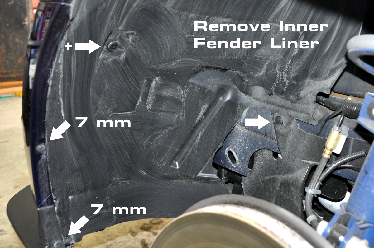


3. Remove inner fender liner. The fender liner is held on with (3) 7 mm bolts and several plastic push-style clips.

4. Relocate electrical harness. Just pull the harness holder from it�s current location and move it up to the hole indicated in the photo.


5. Relocate horns. In simple terms, this just means flipping the horn bracket 180 degrees to gain clearance for the hose. The correct way to do this for maximum clearance and to relieve stress on the electrical harness is to remove the horn assembly (one 7 mm bolt) and lay it on the undertray. Remove the (2) 8 mm nuts holding the bracket to the horns and turn the bracket 180 degrees. Then rotate the horns until the harness and connectors are in a position that will not cause interference with the hose and where there is no stress on the harness. Tighten down the (2) 8 mm nuts and then reinstall the horn assembly with the 7 mm bolt.

Remove the stock bumper valence piece, which can be done easily from the outside with a paint scraper (or similar). Insert a paint scraper behind the part of the bumper valence piece that is towards the middle of the car and use it to pry that side free. Simultaneously, pull on the inside of the foglight blank to free the other side (towards outside of car). The valance piece will pop-out easily.

Insert the hose from the front of the car and check for hose clearance. Also note in this photo that there is no reason to cut the foglight mounts. They do not in any way interfere with the hose. In fact, they fit perfectly against the hose and help secure it in place.

6. Remove brake caliper. Remove the (2) 15 mm bolts that hold the brake caliper to the brake carrier. Use a bungee cord (or similar) to support the weight of the brake caliper. I suspended the caliper from the front spring. Never allow the weight of the caliper to be supported by the brake line! This can cause a failure of the brake line, resulting in catastrophic brake failure!
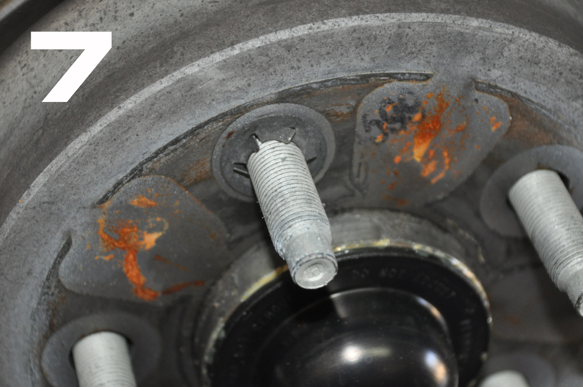
7. Remove brake rotor. The rotor might have these retaining clips that keep the rotor snug against the hub when the wheel is off. I don�t know how to remove these properly, so I used a paint scraper, a flat-head screwdriver, and lots of swearing. After I worked them away from the rotor, I found I could rotate them off. I�m not a fan of unthreaded metal clips on my wheel studs, nor the risk of galling the threads while I am trying to work the clips off. If they were plastic, I would probably like them, but since they aren�t all that useful, I did not reinstall them.

8. Remove splash guard. Remove the (3) 10 mm bolts holding the splash guard to the brake carrier assembly.

9. Install the new backing plate with (3) new 12 mm bolts (included with kit) and torque to 15 ft.-lb.

10. Slide the brake cooling hose over the backing plate and secure with hose clamp (included with kit).

11. Secure hose to body with tie wrap (included in kit). Optionally, you can tie wrap the hose to the anti roll bar. Cut or grind down the plastic undertray shark fins that might cut or abrade the hose.
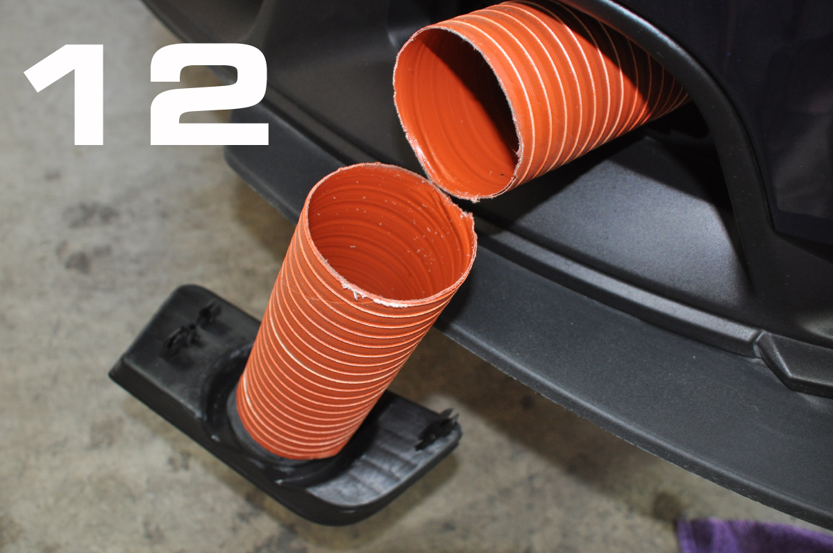
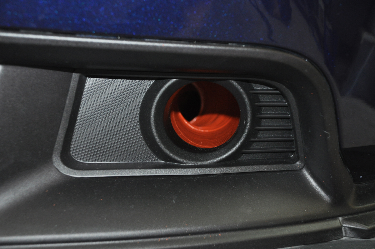
12. Cut excess hose length from front of car. Make sure there is enough free play in the hose to accommodate wheels turned to full lock (both directions) and the suspension at both full droop and full compression. You could skip this step until both sides are done and free play has been fully tested to your satisfaction. Install brake cooling hose to bumper valence insert and secure with hose clamp (included with kit). Push bumper valence insert firmly into place.


13. Cut inner fender liner to clear brake cooling hose. I followed a natural straight line that was in the liner, but it wasn�t quite enough and I had to make another cut to adequately clear the hose. This photo also gives a better view of my tie wrap point and how it holds the hose up off of the cut shark fin.
14. Reinstall inner fender liner.
15. Reinstall brake rotor.
16. Reinstall brake caliper. Apply blue Loctite and torque (2) 15 mm bolts to 85 ft.-lb.
17. Reinstall wheel. Torque (5) 13/16″ lug nuts to 98 ft.-lb.
18. Lower car and recheck all clearance points for interference and free-play.
Instructions for the Right (Passenger) Side:
Instructions for the left (driver) side of the car apply to the right (passenger) side of the car, except that instead of relocating the horn (Step 5), you will want to relocate the windshield washer reservoir. This requires some additional hardware.
COMING SOON!
Last edited by Jimmy Pribble; Oct 6, 2011 at 07:51 PM. Reason: Title
Bullitt Member
Joined: July 1, 2011
Posts: 279
Likes: 0
From: SD
Jimmy,
Nice pics w/ wrench size etc.
Every post makes this install even easier as people build on previous good ideas.
I didn't cut the hoses--they seemed to compress in length, so I left them alone.
I agree, no need to cut foglight mount on driver side. Removing one side from passenger helps curve around washer tank.
Rotor retention clips - use a side cutter to grab a tab, and twist. Do this to a few, then cut the edge of the clip, and they come right off.
Bullitt Member
Joined: January 17, 2011
Posts: 257
Likes: 0
Re-Mounting the Horns
Jimmy,
Nice step-by-step write up; but one question regarding the new horn orientation. I wonder if having the "trumpet" opening facing up is inviting water to fill the horns during rainy weather.
The factory orientation allows them to drain naturally should any water splash up into the opening; but by turning them up you've created a cup to fill with water.
Now I don't know how they're constructed, but I think that if they fill up, they won't work; or will rust over time.
As a solution, how about drilling a 3/16 or 1/4 in hole in the shell at the "bottom" so that they drain before any water builds up in them?
Just a thought..................
Cobra Member
Joined: August 5, 2008
Posts: 1,369
Likes: 0
From: Arvada, CO

Tasca Super Boss 429 Member
Joined: December 18, 2010
Posts: 3,708
Likes: 0
From: NorCal
Jimmy,
Nice step-by-step write up; but one question regarding the new horn orientation. I wonder if having the "trumpet" opening facing up is inviting water to fill the horns during rainy weather.
The factory orientation allows them to drain naturally should any water splash up into the opening; but by turning them up you've created a cup to fill with water.
Now I don't know how they're constructed, but I think that if they fill up, they won't work; or will rust over time.
As a solution, how about drilling a 3/16 or 1/4 in hole in the shell at the "bottom" so that they drain before any water builds up in them?
Just a thought..................
Nice step-by-step write up; but one question regarding the new horn orientation. I wonder if having the "trumpet" opening facing up is inviting water to fill the horns during rainy weather.
The factory orientation allows them to drain naturally should any water splash up into the opening; but by turning them up you've created a cup to fill with water.
Now I don't know how they're constructed, but I think that if they fill up, they won't work; or will rust over time.
As a solution, how about drilling a 3/16 or 1/4 in hole in the shell at the "bottom" so that they drain before any water builds up in them?
Just a thought..................