
Coast Driveline 1-piece aluminum driveshaft install (w/pics)


Coast Driveline 1-piece aluminum driveshaft install (w/pics)
This 'How-To' will cover the installation of the Coast 1-piece aluminum driveshaft.
Tools required
Various metric sockets (10, 12 (12 point), 13, 18mm)
12mm (12 point) ratcheting box end wrench (optional)
12mm (12 point) crows foot extension
Universal joint socket
Socket extensions (various lengths)
Blue Loctite
Torque wrench (up to 76 lb-ft)
Long flat blade screwdriver (or equiv. pry tool)
Brake cleaner (or equiv.)
Straight edge razor blade
Masking tape
Markers (2 different colors)
Estimated install time: 2 to 4 hours
Note: Special instructions added if installing a BMR front safety loop.
Note: Special notes included if you have a MGW shifter and are planning to install a BMR loop.
Installation
1. Jack the vehicle up as high and safe as possible. Always use jack stands!
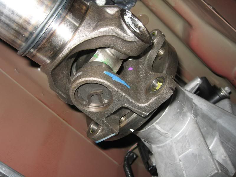
2. Using a suitable marker (I used paper 'white-out'), index mark the 6 o'clock position of the forward transmission output flange and the rear pinion flange.
Using a different color, mark the orientation of the driveshaft to the 2 flanges (in the event the OEM driveshaft is ever reinstalled).
Note: On the rear pinion flange, two 6 o'clock index marks were made, one near the pinion seal and one on the driveshaft's Constant Velocity (CV) joint.
3. With the transmission in neutral, e-brake off, rotate the driveshaft (or have a helper turn the rear tire) for best access to the CV bolts. Set e-brake (so the bolts can be removed).
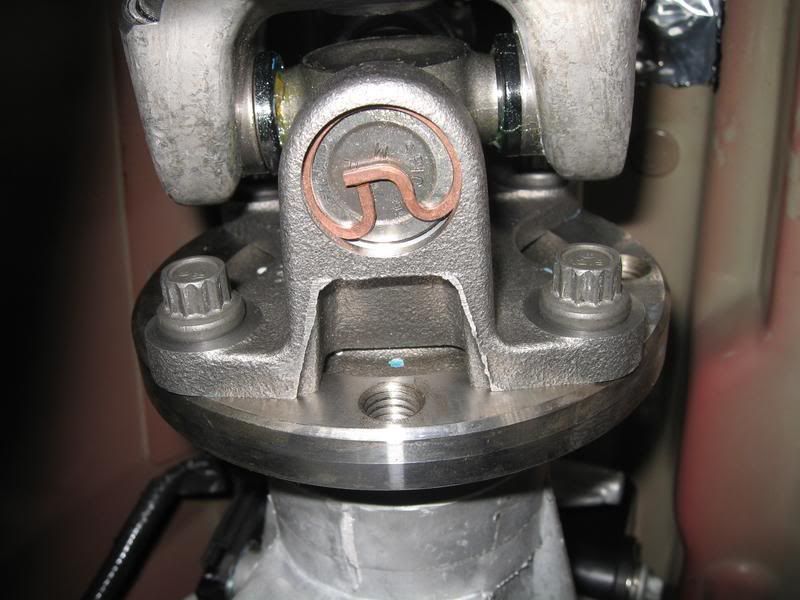
4. Using a 10mm socket, remove the (6) CV joint bolts.
Note: After the removal CV joint washers (the long crescent shaped washer that joints 2 bolts), re-install 3 of the bolts in snug, staggered.

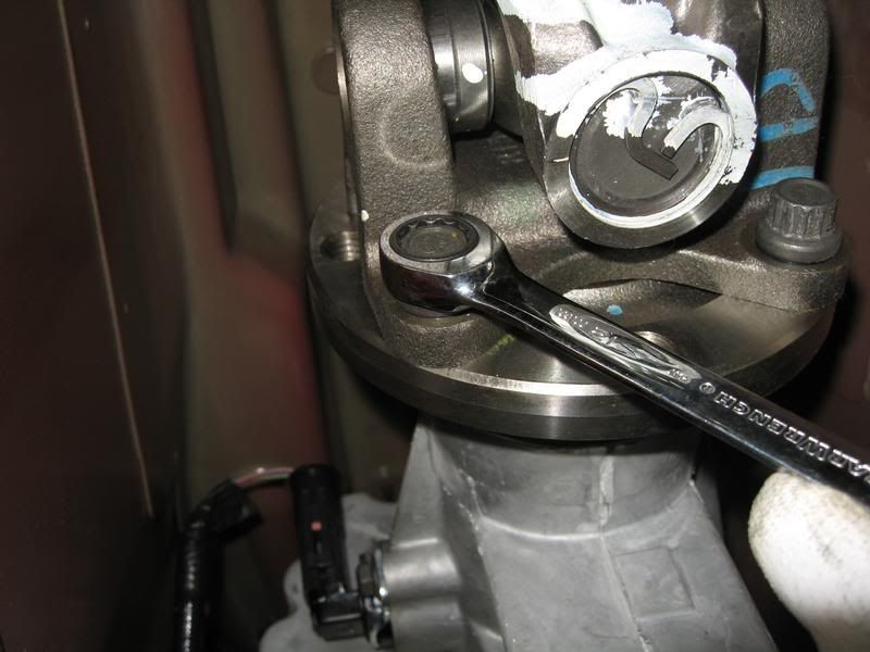
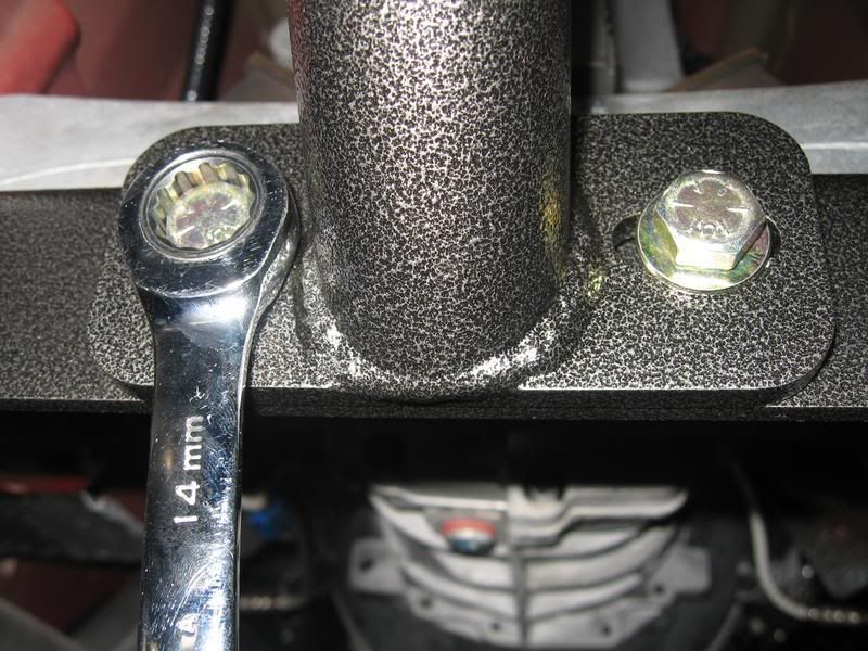
5. Using a 12mm (12 point) socket (or ratcheting wrench), remove the 4 driveshaft flange bolts to the transmission output flange.
Note: Release the e-brake and rotate the driveshaft as necessary to gain access to the bolts. Do not forget to set the e-brake.
Note: Don't worry, the driveshaft will stay put even after all 4 bolts are removed.
Note: Save these 4 bolts, they will be re-used.
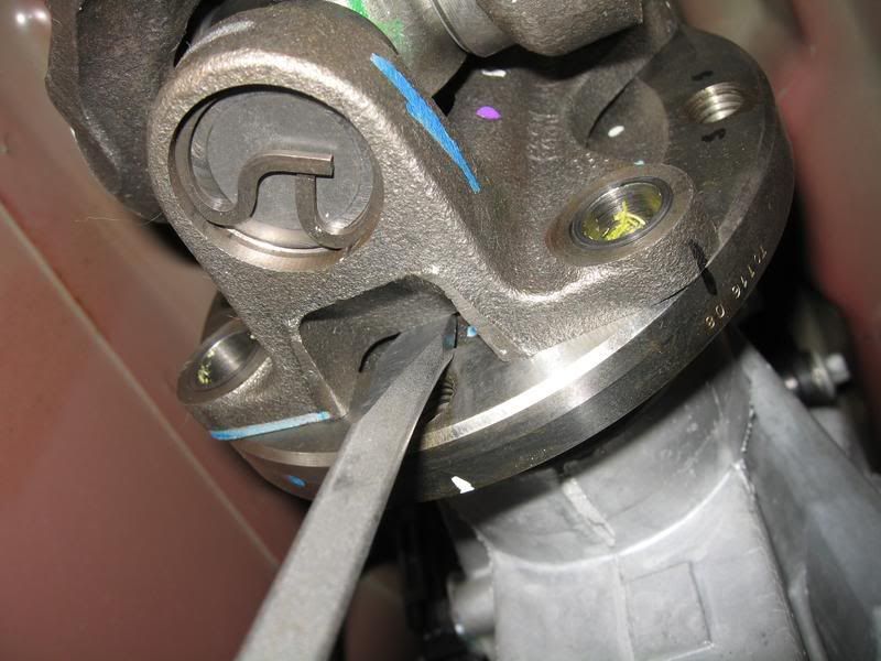
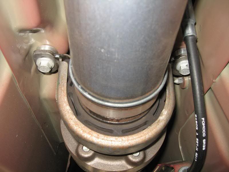
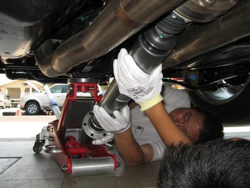
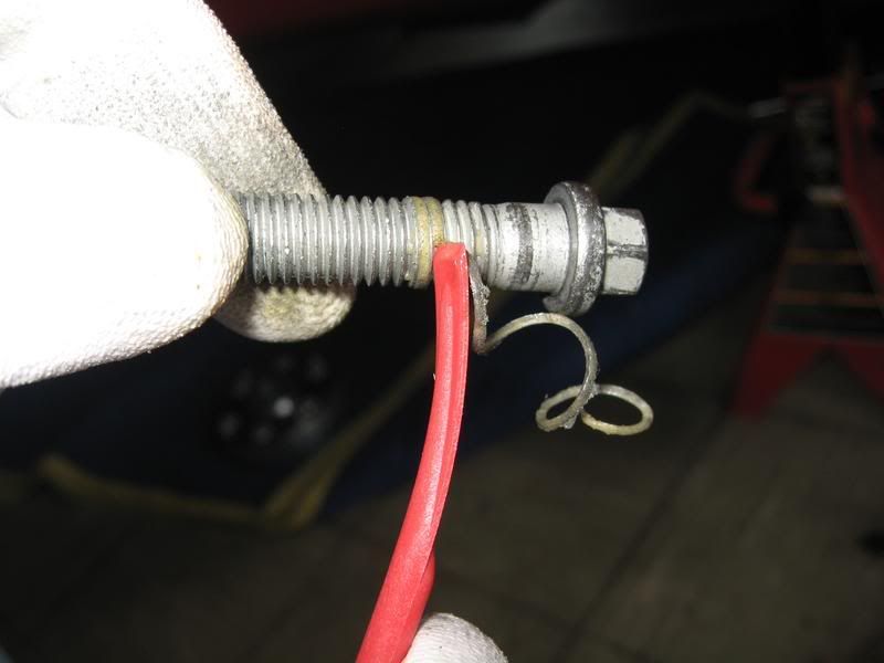
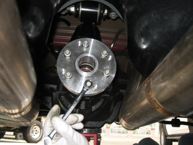
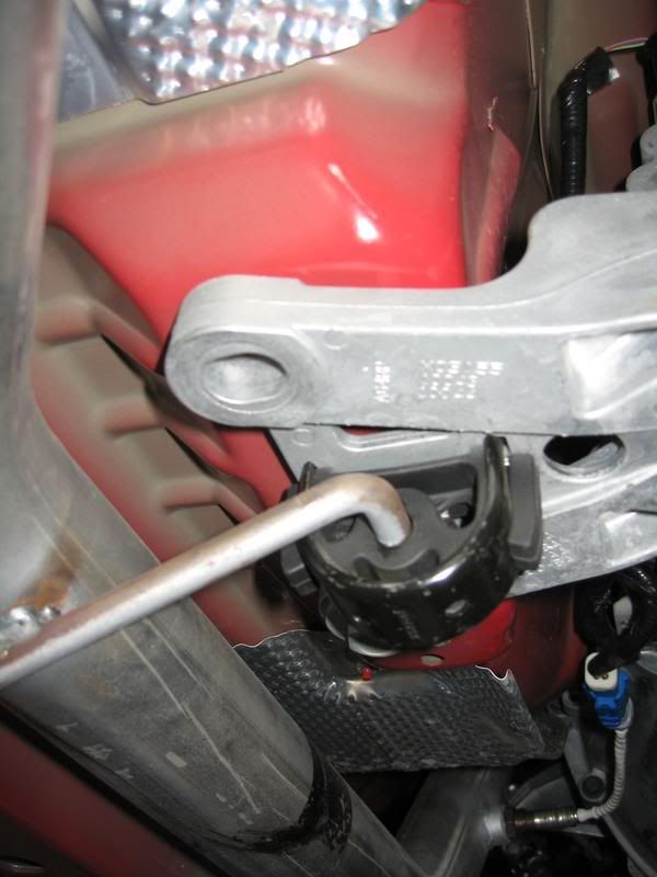
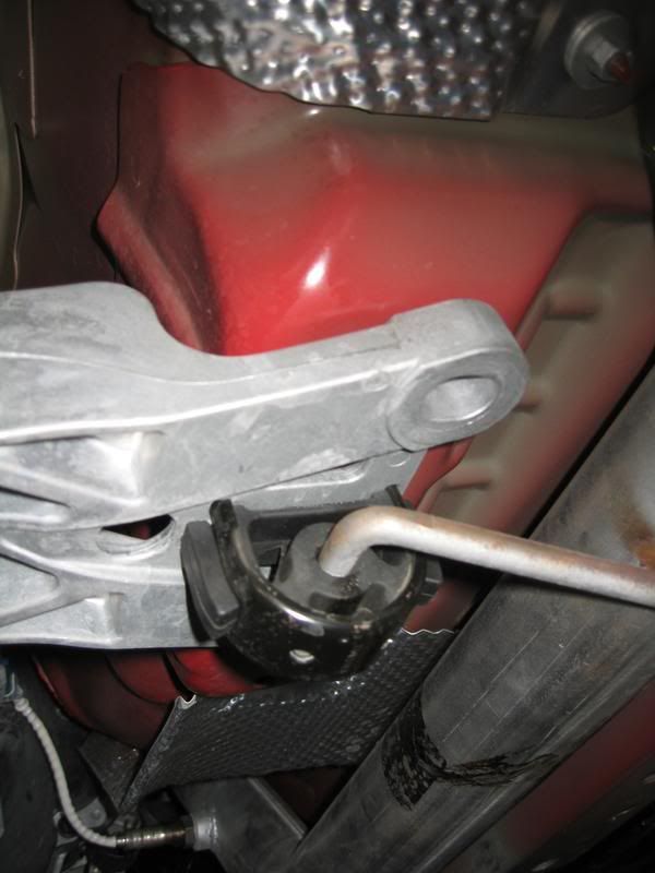
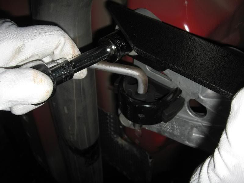
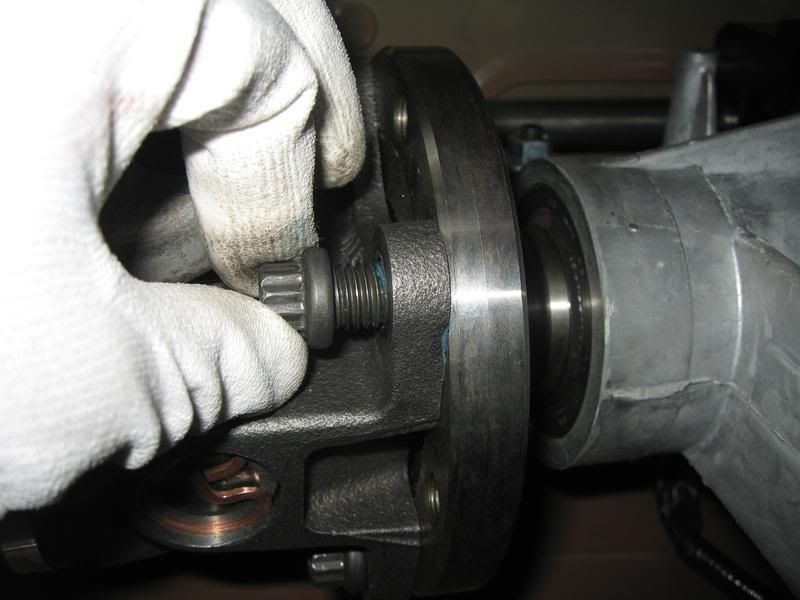
6. Using a suitable pry tool (a flat blade screwdriver worked fine for me), insert it into the U-joint at the position shown. The driveshaft will compress slightly to allow the driveshaft flange to disconnect from the transmission flange.
Leave it in this disconnected state.
Note: Move back to the pinion flange and remove the 3 bolts from step 4 Note.
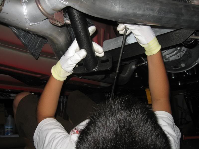
7. Place a couple pieces a 2x4's on top of the mid-pipes to keep the driveshaft from falling onto the pipes once the center bearing bracket is loosened.
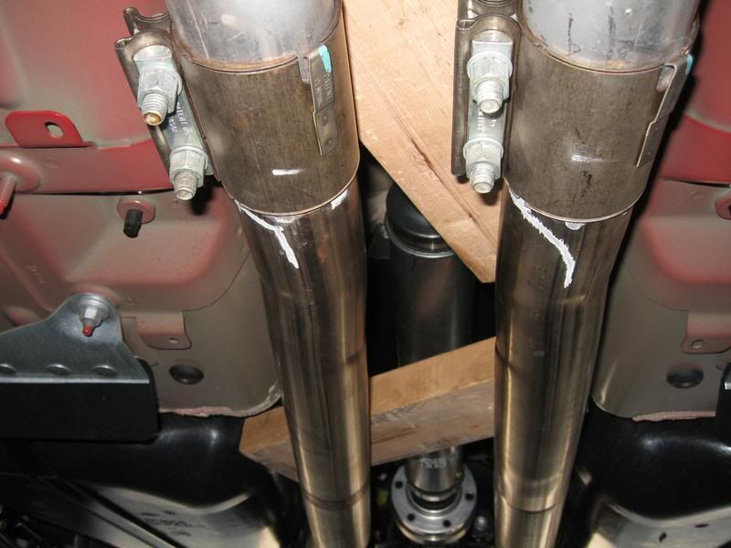
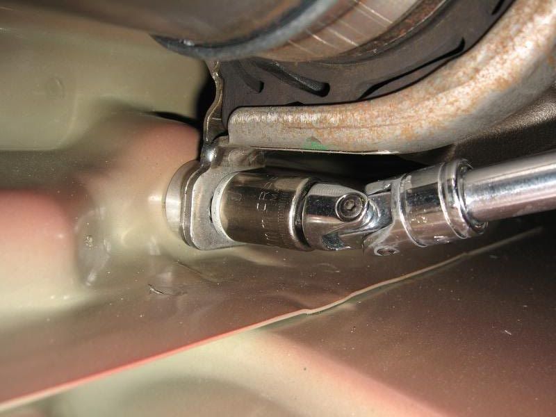
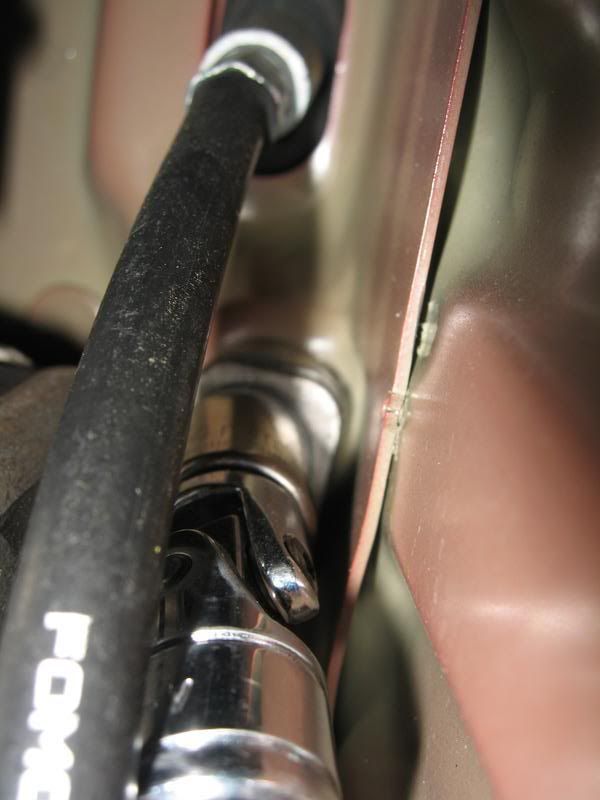
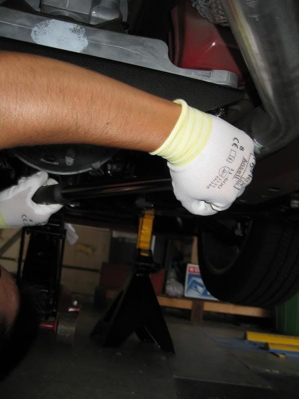
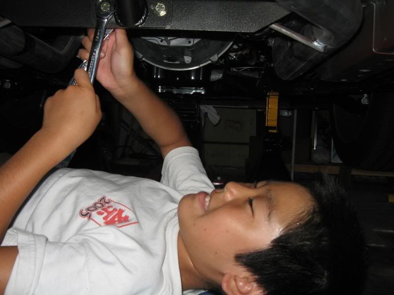
8. Using a 13mm socket (and universal joint adapter if required), remove the 2 bolts from the center bearing bracket (located about mid-way on the driveshaft).

9. Driveshaft is now completely unbolted from the vehicle and now can be positioned to be removed through the rear in-between the mid-pipes.
Note: After the driveshaft is removed, make sure both spacer washers that were under the center bearing bracket are removed off the body.
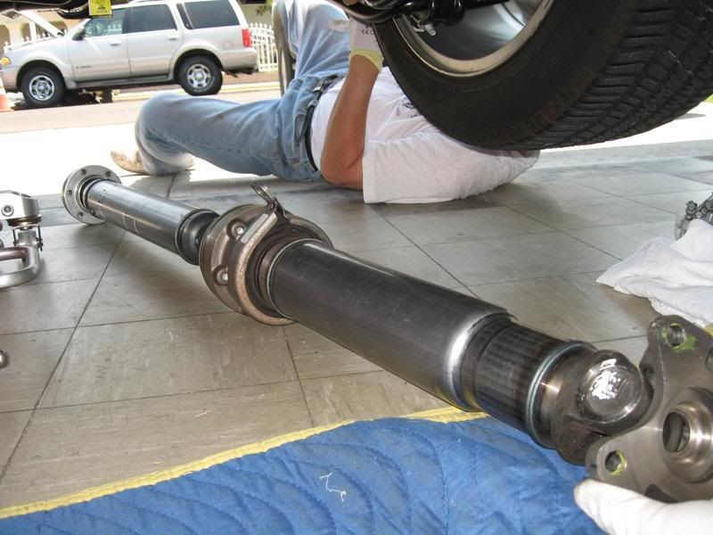
Driveshaft comparison

Pinion Angle
With the driveshaft removed, and if your car is lowered, use an angle gauge to determine what your pinion angle is.
With the car positioned at the same angle as it is on the ground (1/2" forward rake for me with the Steeda Ultralite springs), I jacked the rear pumpkin to the desired height in relation to the front, loading the rear suspension.
Front transmission output flange measured at -3.0 degrees.
Rear pinion flange measured -1 degrees.
If I'm correct, my pinion angle is -2 degrees in relation to the front.
I've been told that Ford's spec on the pinion angle is between -2.75 and -3.0 degrees.
10. Preparation for new driveshaft installation
A thorough cleaning must be done on the rear pinion flange prior to the installation of the adapter plate. According to Coast, the adapter is machined to a zero tolerance fit, so to have it mate against the pinion flange without any debris (Loctite, grease, etc.) in-between is absolutely critical!
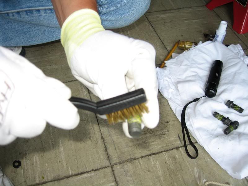
Clean off any thread locker off the threads from the factory CV joint bolts as well as the driveshaft flange bolts.
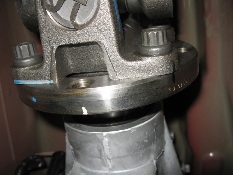
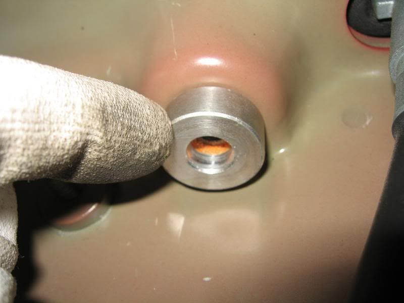
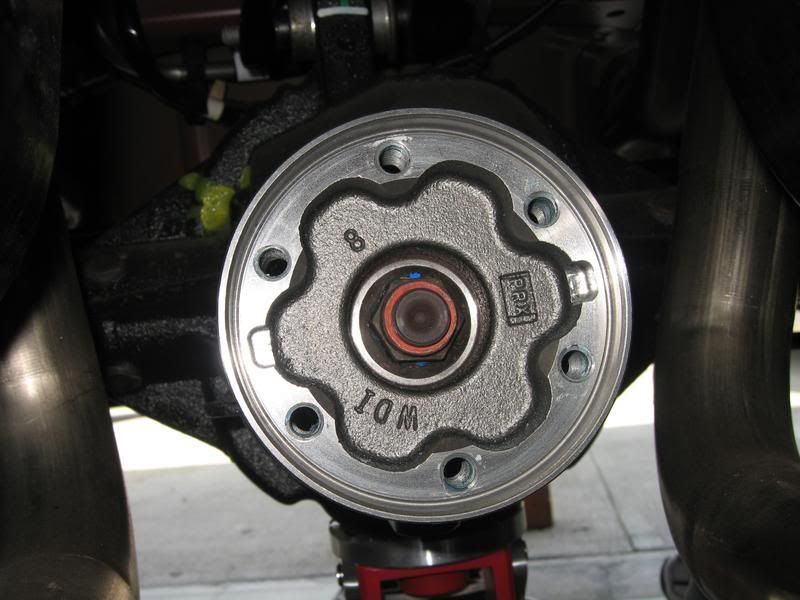
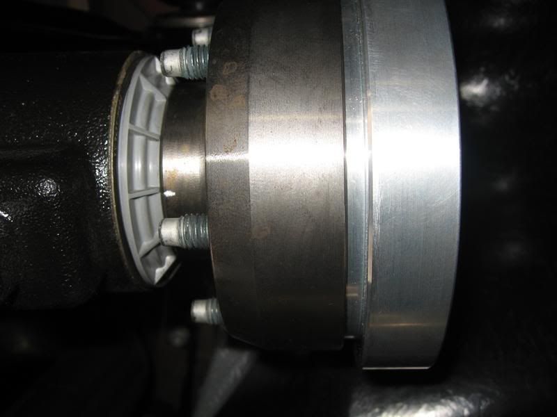
Using a plastic scraper and/or single edge razor, carefully scrape off any dried thread locker off from the pinion flange.
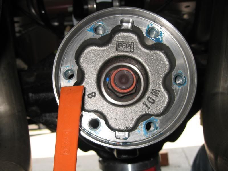
Pinion flange should look as clean as this.
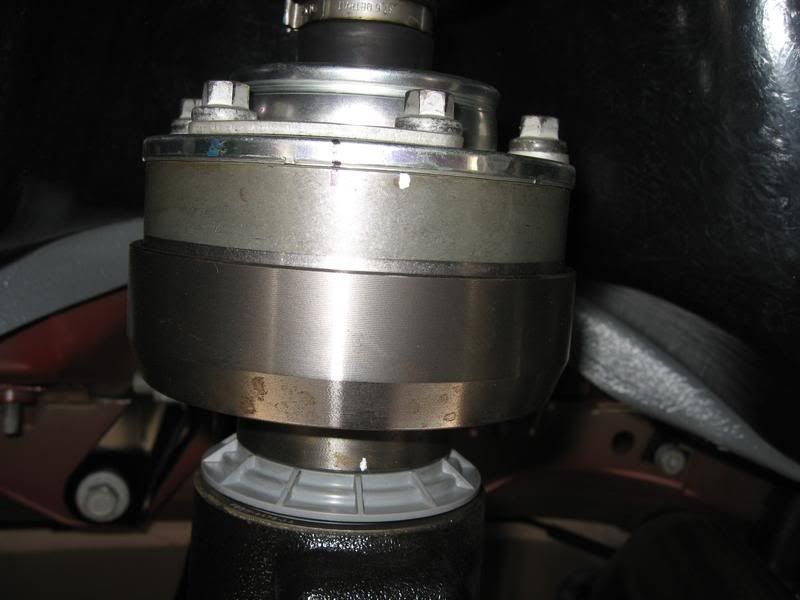
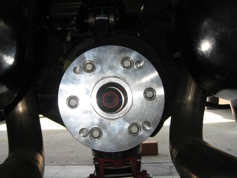
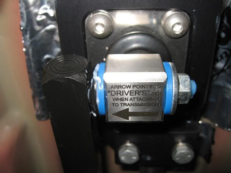
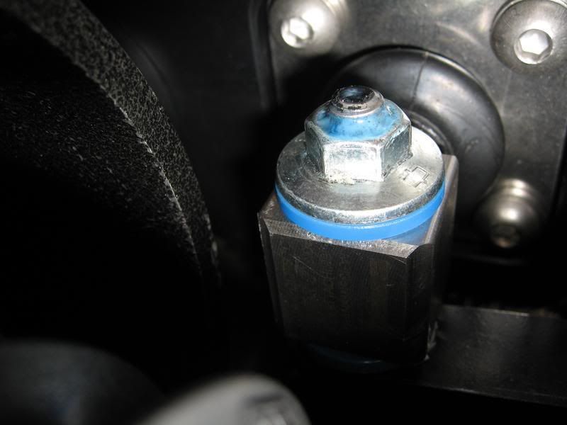
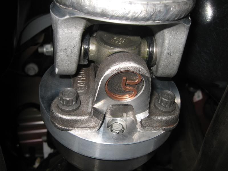
10A. Position the Coast adapter plate into the pinion flange and using the six bolts, evenly draw the adapter into the flange using a standard 'star' torque pattern until all 6 bolts are tight (but, not torqued).
Note: Do not put any Loctite on these bolts yet, must be installed dry at this time to avoid any Loctite from dripping in-between the adapter and pinion flange (Yes, it's that critical!).
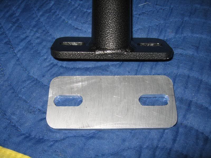
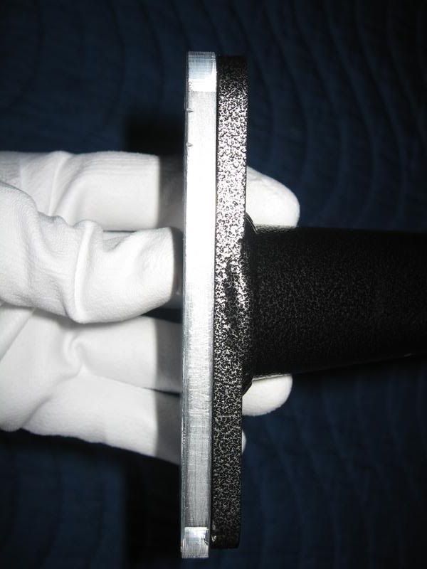
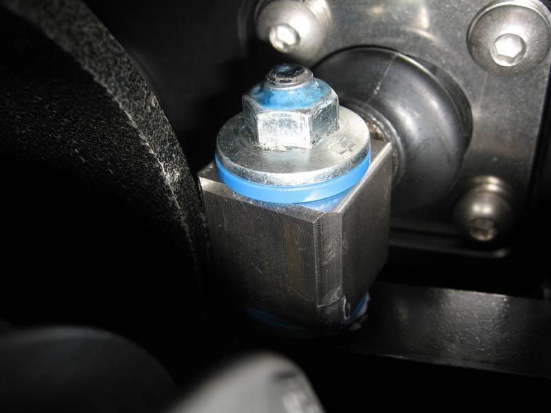
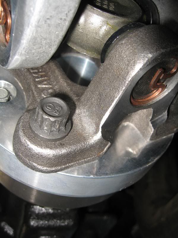
Note: The pinion flange depth is approx. 0.400" and the adapter step (that get's inserted) is approx. 0.550". So when drawn down and mated, about a 0.150" gap on the adapter will be visible.
Note: To ensure the adapter is fully and evenly seated onto the pinion flange, rig up a magnetic dial indicator (or hold stationary anything non-metallic) and have a helper turn the tires to check for flatness/trueness on the face of the adapter.
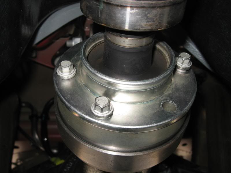
10B. Once the adapter plate is fully seated, remove one bolt at a time and apply Loctite on the threads, re-install, and torque to 41 lb-ft.
Note: I used a piece of masking tape to mark each bolt that I Locktited and torqued to avoid any confusion.
All 6 CV joint bolts installed.
Continued on Post 2...
Tools required
Various metric sockets (10, 12 (12 point), 13, 18mm)
12mm (12 point) ratcheting box end wrench (optional)
12mm (12 point) crows foot extension
Universal joint socket
Socket extensions (various lengths)
Blue Loctite
Torque wrench (up to 76 lb-ft)
Long flat blade screwdriver (or equiv. pry tool)
Brake cleaner (or equiv.)
Straight edge razor blade
Masking tape
Markers (2 different colors)
Estimated install time: 2 to 4 hours
Note: Special instructions added if installing a BMR front safety loop.
Note: Special notes included if you have a MGW shifter and are planning to install a BMR loop.
Installation
1. Jack the vehicle up as high and safe as possible. Always use jack stands!
2. Using a suitable marker (I used paper 'white-out'), index mark the 6 o'clock position of the forward transmission output flange and the rear pinion flange.
Using a different color, mark the orientation of the driveshaft to the 2 flanges (in the event the OEM driveshaft is ever reinstalled).
Note: On the rear pinion flange, two 6 o'clock index marks were made, one near the pinion seal and one on the driveshaft's Constant Velocity (CV) joint.
3. With the transmission in neutral, e-brake off, rotate the driveshaft (or have a helper turn the rear tire) for best access to the CV bolts. Set e-brake (so the bolts can be removed).
4. Using a 10mm socket, remove the (6) CV joint bolts.
Note: After the removal CV joint washers (the long crescent shaped washer that joints 2 bolts), re-install 3 of the bolts in snug, staggered.
5. Using a 12mm (12 point) socket (or ratcheting wrench), remove the 4 driveshaft flange bolts to the transmission output flange.
Note: Release the e-brake and rotate the driveshaft as necessary to gain access to the bolts. Do not forget to set the e-brake.
Note: Don't worry, the driveshaft will stay put even after all 4 bolts are removed.
Note: Save these 4 bolts, they will be re-used.
6. Using a suitable pry tool (a flat blade screwdriver worked fine for me), insert it into the U-joint at the position shown. The driveshaft will compress slightly to allow the driveshaft flange to disconnect from the transmission flange.
Leave it in this disconnected state.
Note: Move back to the pinion flange and remove the 3 bolts from step 4 Note.
7. Place a couple pieces a 2x4's on top of the mid-pipes to keep the driveshaft from falling onto the pipes once the center bearing bracket is loosened.
8. Using a 13mm socket (and universal joint adapter if required), remove the 2 bolts from the center bearing bracket (located about mid-way on the driveshaft).
9. Driveshaft is now completely unbolted from the vehicle and now can be positioned to be removed through the rear in-between the mid-pipes.
Note: After the driveshaft is removed, make sure both spacer washers that were under the center bearing bracket are removed off the body.
Driveshaft comparison
Pinion Angle
With the driveshaft removed, and if your car is lowered, use an angle gauge to determine what your pinion angle is.
With the car positioned at the same angle as it is on the ground (1/2" forward rake for me with the Steeda Ultralite springs), I jacked the rear pumpkin to the desired height in relation to the front, loading the rear suspension.
Front transmission output flange measured at -3.0 degrees.
Rear pinion flange measured -1 degrees.
If I'm correct, my pinion angle is -2 degrees in relation to the front.
I've been told that Ford's spec on the pinion angle is between -2.75 and -3.0 degrees.
10. Preparation for new driveshaft installation
A thorough cleaning must be done on the rear pinion flange prior to the installation of the adapter plate. According to Coast, the adapter is machined to a zero tolerance fit, so to have it mate against the pinion flange without any debris (Loctite, grease, etc.) in-between is absolutely critical!
Clean off any thread locker off the threads from the factory CV joint bolts as well as the driveshaft flange bolts.
Using a plastic scraper and/or single edge razor, carefully scrape off any dried thread locker off from the pinion flange.
Pinion flange should look as clean as this.
10A. Position the Coast adapter plate into the pinion flange and using the six bolts, evenly draw the adapter into the flange using a standard 'star' torque pattern until all 6 bolts are tight (but, not torqued).
Note: Do not put any Loctite on these bolts yet, must be installed dry at this time to avoid any Loctite from dripping in-between the adapter and pinion flange (Yes, it's that critical!).
Note: The pinion flange depth is approx. 0.400" and the adapter step (that get's inserted) is approx. 0.550". So when drawn down and mated, about a 0.150" gap on the adapter will be visible.
Note: To ensure the adapter is fully and evenly seated onto the pinion flange, rig up a magnetic dial indicator (or hold stationary anything non-metallic) and have a helper turn the tires to check for flatness/trueness on the face of the adapter.
10B. Once the adapter plate is fully seated, remove one bolt at a time and apply Loctite on the threads, re-install, and torque to 41 lb-ft.
Note: I used a piece of masking tape to mark each bolt that I Locktited and torqued to avoid any confusion.
All 6 CV joint bolts installed.
Continued on Post 2...
Last edited by TacoBill; Mar 13, 2008 at 08:37 AM. Reason: sp
(Continued...)
Special Section: BMR front safety loop
Whether you need a safety loop is all up to you.
Here's NHRA's take on it..
A driveshaft loop will be required on all cars running 13.99 or quicker and utilizing slicks, except vehicles equipped with street tires running 11.49 or slower.
For those installing a BMR front safety loop, see the installation steps below.
For those not installing a safety loop, skip to step 11.
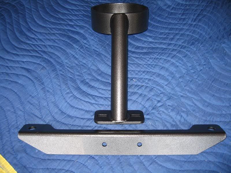
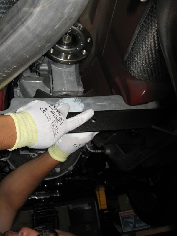
BMR1. Remove the 2 rear transmission crossmember bolts using an 18mm socket
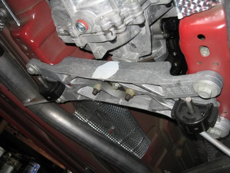
BMR2. Mount the BMR driveshaft loop mounting crossmember to the transmission crossmember, re-install the factory bolts and torque to 55 lb-ft.
BMR3. Insert the new drive shaft though the BMR loop and let it hang until the 4 bolts on the driveshaft flange to the transmission output flange are installed and torqued complete.
(no picture)
BMR4. Mount the loop portion to the crossmember portion using the supplied bolts and nuts.
BMR5. Position the loop so it's even on both sides of the driveshaft (can use you fingers to check for even gap).
(no picture)
BMR6. Tighten the 2 bolts and ensure the even gap is maintained.
Special Section: MGW Short Throw Shifter
If you have a MGW shifter, the BMR loop will interfere with the adjustable shifter block on the 1-3-5 shifts.
To eliminate this riding condition, you'll need to fabricate a shim that will be placed between the BMR crossmember and the safety loop.
A 0.250" (1/4") shim was fabricated, but the shifter block just barely makes contact with the loop on the 1 shift (3 & 5 do not make contact).
Note: The supplied BMR bolts will be too short with the addition of a shim. Longer bolts will be needed to accommodate the shim and to allow at least 2-3 threads to protrude past the plane of the nut.
I recommend obtaining either 1�" or 1�" long Grade 8 bolts (BMR supplied bolts are 1" long).
Note: I have the shifter block turned all the way in (then backed out to align the black arrow to the drivers side) at zero turns to give as much clearance to the loop as possible. Throw is a tad longer than what I had at 6 turns, but still feels very good and is still shorter than the stock throw.

Neutral
1st Gear
Note: With the rear suspension unloaded and with the 0.250" shim in place, there is a 0.390" gap between the bottom of the driveshaft and the loop. So this means that I can afford to go with a thicker shim (I'm thinking 0.350" think) to eliminate the 1st gear interference and still have a gap between the loop and driveshaft.
I have not tried this yet, but when I do, I will update this thread.
Edit:
New 0.350" shim is in place along with longer Grade 8 bolts (1 1/2" long) and everything is fine, no riding conditions between the safety loop and MGW shifter block.
Note: To all.. after helping with a few BMR-MGW installs, I recommend going with a 0.380" shim to be on the safe side.
I was able to safely turn the shifter block out to 5 turns too.
11. New driveshaft installation
With the e-brake off, index the 6 o'clock marks you made on the pinion flange and transmission output flange.
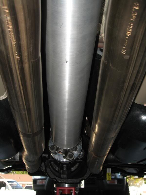
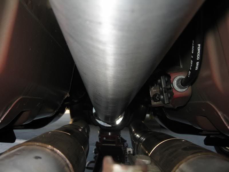
Position the new driveshaft up from the rear in-between the mid-pipes and carefully route up to the front.
Place rags over any sharp objects to avoid scratching the new aluminum driveshaft.
Note: If you accidentally ding any part of the driveshaft, STOP your installation and contact Coast at 800-533-8087 for advisement.
Let me put it this way, my first driveshaft arrived with a small, smooth dent (thanks to UPS) and Coast flat out rejected it for use.
Mate up both ends of the driveshaft's U-joints against the rear pinion adapter plate and the forward transmission output flange.
Rotate the driveshaft if necessary to pick up the previously used 4 bolt holes in the transmission output flange, and make sure the 6 o'clock markings didn't move while rotating the driveshaft.
Once everything is in position, Loctite each bolt and snug down tight. Using an 'X' pattern, torque the bolts to the following;
Driveshaft to transmission output flange: 76 lb-ft
Driveshaft to pinion adapter plate: 41 lb-ft
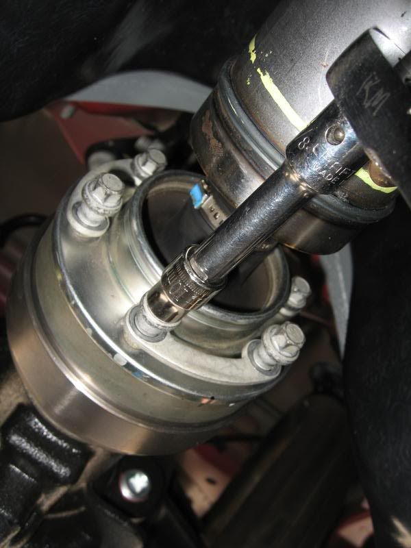
Note: A standard socket - universal joint adapter - ratchet combo will not fit squarely on the U-joint bolts. Correctly torquing these bolts will be difficult without a 12 point Crow's Foot extension (or equiv.).
If you choose to use an extension, use the following formula to set your correct torque value.
(T x L) / (L + E) = Adjusted torque value (what you set on your torque wrench)
T= target torque value
L= length of torque wrench in inches (end of handle to center of socket)
E= length of extension in inches (center of socket to center of bolt)
If using a 1" Crow's Foot extension on the front U-joint bolts, here's the way the formula works out.
(76 x 12" torque wrench) / (12" torque wrench + 1" extension) = 70.15 lb-in torque. This is what you would set the torque wrench to.
Installation complete!
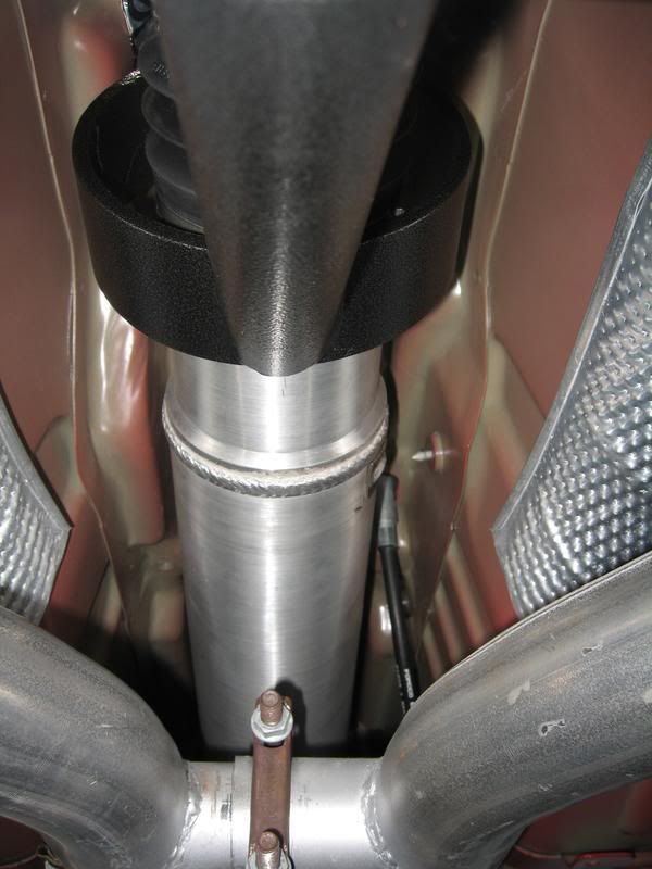
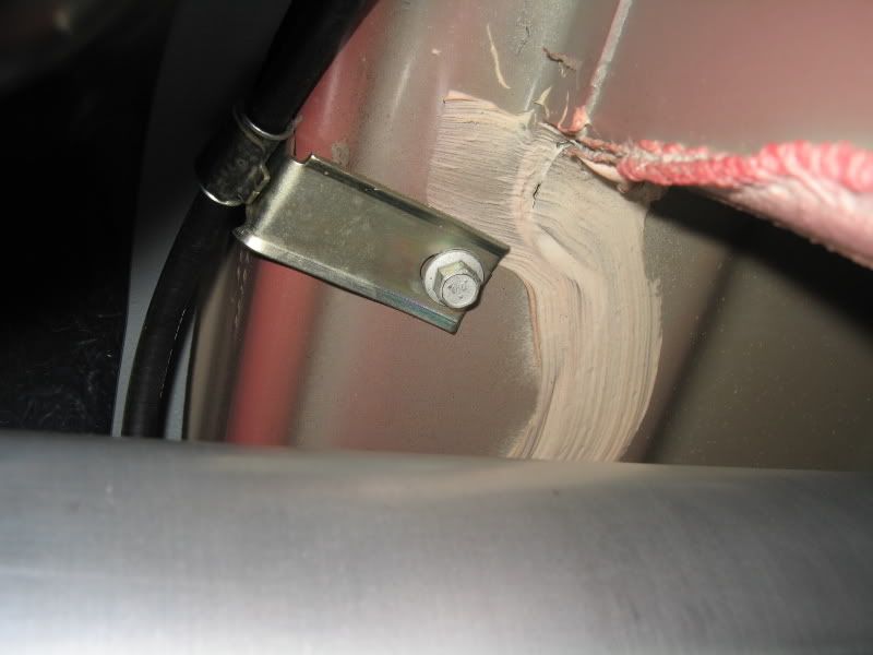
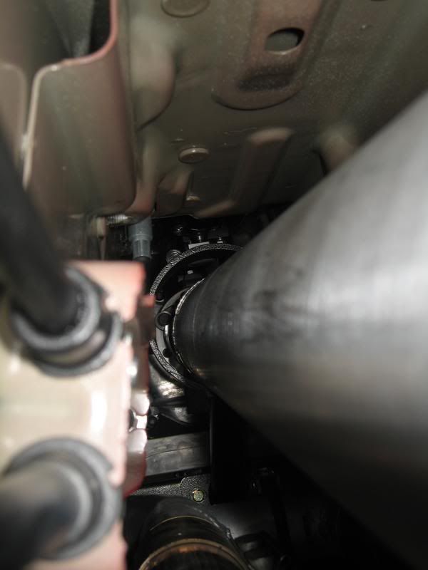
Note: According to Coast's written instructions as well as a few online sources, there seems to be a clearance issue between the e-brake cable bracket and the driveshaft. Instructions will have you re-drill the bracket bolt hole and move it 1.5" away from the driveshaft tunnel.
On my 2006, I don't see any bolt attaching the bracket to the tunnel. Instead, it looks to be spot welded on or something, nor do I see no clearance issues between these two. With the rear suspension unloaded, there's a good amount of clearance between the bracket and cable to the driveshaft so I don't see a need to relocate this bracket.
*Edit*
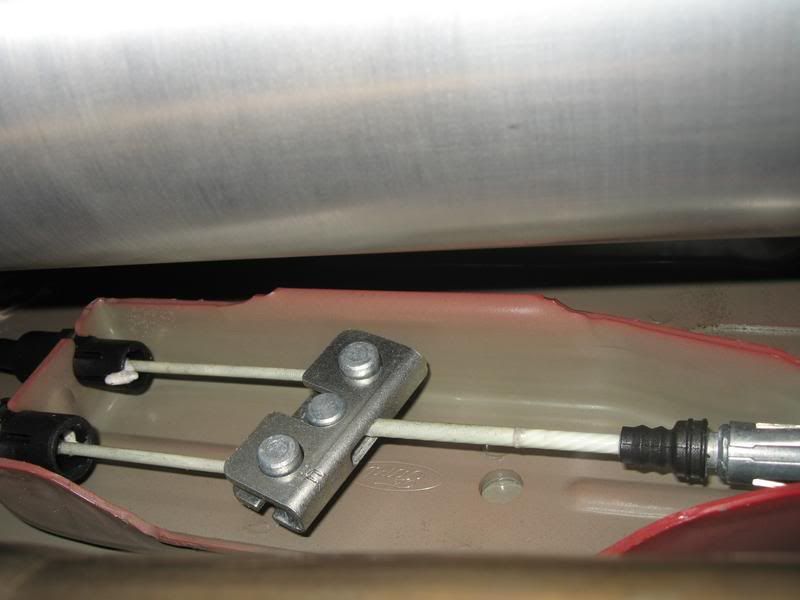
I think I know which bracket they're talking about now. It's a small support clip/bracket that supports the e-brake cable that goes to the passenger side brake. On an aggressively lowered car, I can possibly see some clearance issues to the bolt head of that clip/bracket if not re-located.
See pic below for reference.
New update:
Took the car out for a short test drive mainly to check for anything wierd (vibrations, etc.). Couldn't open her up on the highway because of traffic, but I went to my secret proving grounds and got up to 80 and no vibrations!
Update #2:
Riding condition & e-brake bracket relo instructions added.
See post 59 for detailed info.
Special Section: BMR front safety loop
Whether you need a safety loop is all up to you.
Here's NHRA's take on it..
A driveshaft loop will be required on all cars running 13.99 or quicker and utilizing slicks, except vehicles equipped with street tires running 11.49 or slower.
For those installing a BMR front safety loop, see the installation steps below.
For those not installing a safety loop, skip to step 11.
BMR1. Remove the 2 rear transmission crossmember bolts using an 18mm socket
BMR2. Mount the BMR driveshaft loop mounting crossmember to the transmission crossmember, re-install the factory bolts and torque to 55 lb-ft.
BMR3. Insert the new drive shaft though the BMR loop and let it hang until the 4 bolts on the driveshaft flange to the transmission output flange are installed and torqued complete.
(no picture)
BMR4. Mount the loop portion to the crossmember portion using the supplied bolts and nuts.
BMR5. Position the loop so it's even on both sides of the driveshaft (can use you fingers to check for even gap).
(no picture)
BMR6. Tighten the 2 bolts and ensure the even gap is maintained.
Special Section: MGW Short Throw Shifter
If you have a MGW shifter, the BMR loop will interfere with the adjustable shifter block on the 1-3-5 shifts.
To eliminate this riding condition, you'll need to fabricate a shim that will be placed between the BMR crossmember and the safety loop.
A 0.250" (1/4") shim was fabricated, but the shifter block just barely makes contact with the loop on the 1 shift (3 & 5 do not make contact).
Note: The supplied BMR bolts will be too short with the addition of a shim. Longer bolts will be needed to accommodate the shim and to allow at least 2-3 threads to protrude past the plane of the nut.
I recommend obtaining either 1�" or 1�" long Grade 8 bolts (BMR supplied bolts are 1" long).
Note: I have the shifter block turned all the way in (then backed out to align the black arrow to the drivers side) at zero turns to give as much clearance to the loop as possible. Throw is a tad longer than what I had at 6 turns, but still feels very good and is still shorter than the stock throw.
Neutral
1st Gear
Note: With the rear suspension unloaded and with the 0.250" shim in place, there is a 0.390" gap between the bottom of the driveshaft and the loop. So this means that I can afford to go with a thicker shim (I'm thinking 0.350" think) to eliminate the 1st gear interference and still have a gap between the loop and driveshaft.
I have not tried this yet, but when I do, I will update this thread.
Edit:
New 0.350" shim is in place along with longer Grade 8 bolts (1 1/2" long) and everything is fine, no riding conditions between the safety loop and MGW shifter block.
Note: To all.. after helping with a few BMR-MGW installs, I recommend going with a 0.380" shim to be on the safe side.
I was able to safely turn the shifter block out to 5 turns too.
11. New driveshaft installation
With the e-brake off, index the 6 o'clock marks you made on the pinion flange and transmission output flange.
Position the new driveshaft up from the rear in-between the mid-pipes and carefully route up to the front.
Place rags over any sharp objects to avoid scratching the new aluminum driveshaft.
Note: If you accidentally ding any part of the driveshaft, STOP your installation and contact Coast at 800-533-8087 for advisement.
Let me put it this way, my first driveshaft arrived with a small, smooth dent (thanks to UPS) and Coast flat out rejected it for use.
Mate up both ends of the driveshaft's U-joints against the rear pinion adapter plate and the forward transmission output flange.
Rotate the driveshaft if necessary to pick up the previously used 4 bolt holes in the transmission output flange, and make sure the 6 o'clock markings didn't move while rotating the driveshaft.
Once everything is in position, Loctite each bolt and snug down tight. Using an 'X' pattern, torque the bolts to the following;
Driveshaft to transmission output flange: 76 lb-ft
Driveshaft to pinion adapter plate: 41 lb-ft
Note: A standard socket - universal joint adapter - ratchet combo will not fit squarely on the U-joint bolts. Correctly torquing these bolts will be difficult without a 12 point Crow's Foot extension (or equiv.).
If you choose to use an extension, use the following formula to set your correct torque value.
(T x L) / (L + E) = Adjusted torque value (what you set on your torque wrench)
T= target torque value
L= length of torque wrench in inches (end of handle to center of socket)
E= length of extension in inches (center of socket to center of bolt)
If using a 1" Crow's Foot extension on the front U-joint bolts, here's the way the formula works out.
(76 x 12" torque wrench) / (12" torque wrench + 1" extension) = 70.15 lb-in torque. This is what you would set the torque wrench to.
Installation complete!
Note: According to Coast's written instructions as well as a few online sources, there seems to be a clearance issue between the e-brake cable bracket and the driveshaft. Instructions will have you re-drill the bracket bolt hole and move it 1.5" away from the driveshaft tunnel.
On my 2006, I don't see any bolt attaching the bracket to the tunnel. Instead, it looks to be spot welded on or something, nor do I see no clearance issues between these two. With the rear suspension unloaded, there's a good amount of clearance between the bracket and cable to the driveshaft so I don't see a need to relocate this bracket.
*Edit*
I think I know which bracket they're talking about now. It's a small support clip/bracket that supports the e-brake cable that goes to the passenger side brake. On an aggressively lowered car, I can possibly see some clearance issues to the bolt head of that clip/bracket if not re-located.
See pic below for reference.
New update:
Took the car out for a short test drive mainly to check for anything wierd (vibrations, etc.). Couldn't open her up on the highway because of traffic, but I went to my secret proving grounds and got up to 80 and no vibrations!
Update #2:
Riding condition & e-brake bracket relo instructions added.
See post 59 for detailed info.
Last edited by TacoBill; Mar 13, 2008 at 08:47 AM. Reason: new updates added.

So far, my driving with the new driveshaft has been limited to backing it out of the garage and re-parking it back in. 
Sorry Scott, no high speed or hard launch tests until I get a thicker shim is made up and the longer bolts it (on the BMR loop).
But don't worry, I'll post my SOTP results ASAP.
Sorry Scott, no high speed or hard launch tests until I get a thicker shim is made up and the longer bolts it (on the BMR loop).
But don't worry, I'll post my SOTP results ASAP.
Legacy TMS Member
Joined: January 9, 2005
Posts: 6,982
Likes: 6
From: New Carlisle, Ohio (20 miles north of Dayton)
So far, my driving with the new driveshaft has been limited to backing it out of the garage and re-parking it back in.
Sorry Scott, no high speed or hard launch tests until I get a thicker shim is made up and the longer bolts it (on the BMR loop).
But don't worry, I'll post my SOTP results ASAP.
Sorry Scott, no high speed or hard launch tests until I get a thicker shim is made up and the longer bolts it (on the BMR loop).
But don't worry, I'll post my SOTP results ASAP.
Scott


Legacy TMS Member
Joined: October 8, 2005
Posts: 12,395
Likes: 29
From: Medina county, OH
Hahaha good one Scott...... Yes Bill get back to us with your driving impressions. I'm gonna guess that they're pretty similar to others, but another opinion is always good.
Team Mustang Source
Joined: December 12, 2004
Posts: 5,801
Likes: 5
From: NorCal
Thanks for the write up Bill. I don't have the Coast shaft but I am installing the Spyder shaft on the 11th as well as the BMR front safety loop. Your write up should be very helpful. I also wait to hear what your impression are after letting it rip a few times.
Once you get that pinion flange installed for your Spyder, everything else should be cake.
Bullitt Member
Joined: November 16, 2006
Posts: 434
Likes: 0
From: Knoxville, TN
Thats what we did with mine and there is plenty of clearance now with the MGW.
If you do have the MGW shifter and are installing the BMR front loop, you don't have to fab anything up. Just use these 2 spacers between the BMR crossmember & the loop part and it will work fine.
Thats what we did with mine and there is plenty of clearance now with the MGW.
Thats what we did with mine and there is plenty of clearance now with the MGW.
Those spacer washers do look a tad over 0.250" thick, so I'm sure they do the trick. I'm still going to go ahead and fab up a plate shim just to beef things up just incase that loop has to do it's job one day.
btw, with those spacers in your car, how many turns out is your shifter block set to?

Bullitt Member
Joined: November 16, 2006
Posts: 434
Likes: 0
From: Knoxville, TN
Funny, I was thinking about doing that in my time of crisis.
Those spacer washers do look a tad over 0.250" thick, so I'm sure they do the trick. I'm still going to go ahead and fab up a plate shim just to beef things up just incase that loop has to do it's job one day.
btw, with those spacers in your car, how many turns out is your shifter block set to?
Those spacer washers do look a tad over 0.250" thick, so I'm sure they do the trick. I'm still going to go ahead and fab up a plate shim just to beef things up just incase that loop has to do it's job one day.
btw, with those spacers in your car, how many turns out is your shifter block set to?
Team Mustang Source
Joined: January 5, 2005
Posts: 13,223
Likes: 14
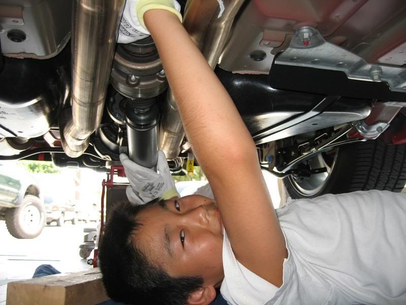
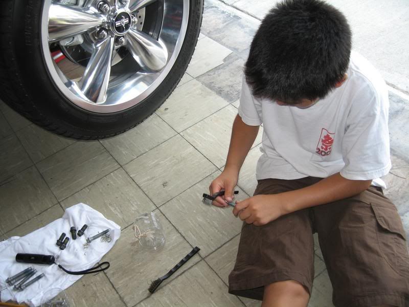
Hey has nobody noticed the excellent handy work by Chris ! and those gloves CSI could not find evidence on the from the Garage Queen If I were super rich I'd want Bill for a private mod/mechanic .
You made this all seem so simple and if your liking said end result then I will have to be a copy cat.
You made this all seem so simple and if your liking said end result then I will have to be a copy cat.
Former Vendor
Joined: January 11, 2007
Posts: 2,594
Likes: 0
From: Aston, PA