
Meziere install and the relay ignition-on sense wire

Mach 1 Member
Joined: December 5, 2004
Posts: 665
Likes: 0
Originally Posted by dustindu4
It's right but the add-a-line only has 1 wire on it, the other relay pin should be grounded
Here's my revised diagram:
I hope that's correct.
The only improvement I can see is if the pump was powered only when the engine is running or optionally if a manual switch was activated (if the engine is not running). With the current setup, one risks drainning the battery if one listens to the radio/CD (with the key in) and the engine off - I think somebody mentioned that.
9 is not my lucky number.
Joined: March 12, 2004
Posts: 3,663
Likes: 1
Originally Posted by LordBritish
Oh, I see.
Here's my revised diagram:
I hope that's correct.
The only improvement I can see is if the pump was powered only when the engine is running or optionally if a manual switch was activated (if the engine is not running). With the current setup, one risks drainning the battery if one listens to the radio/CD (with the key in) and the engine off - I think somebody mentioned that.
you can listen to the radio without turning the key all the way, radio goes on with a half turn
Thread Starter
Team Mustang Source
Joined: October 11, 2004
Posts: 711
Likes: 0
From: Surrey, BC
Originally Posted by LordBritish
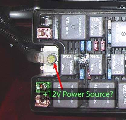
Do I merely wrap a portion of stripped wire around that bolt and tighten it or is there a more reliable method of making contact?
Thread Starter
Team Mustang Source
Joined: October 11, 2004
Posts: 711
Likes: 0
From: Surrey, BC
I believe yellow is typically a 10-12ga, blue is 14-16ga and red is 18-22ga.
I have blue ones (14-16ga) that fit there but I'll be using a yellow as the main wire from the relay kit is 12ga.
I have blue ones (14-16ga) that fit there but I'll be using a yellow as the main wire from the relay kit is 12ga.
Mach 1 Member
Joined: December 5, 2004
Posts: 665
Likes: 0
Lots of little details !!!
One more noob question about that Add-A-Circuit.
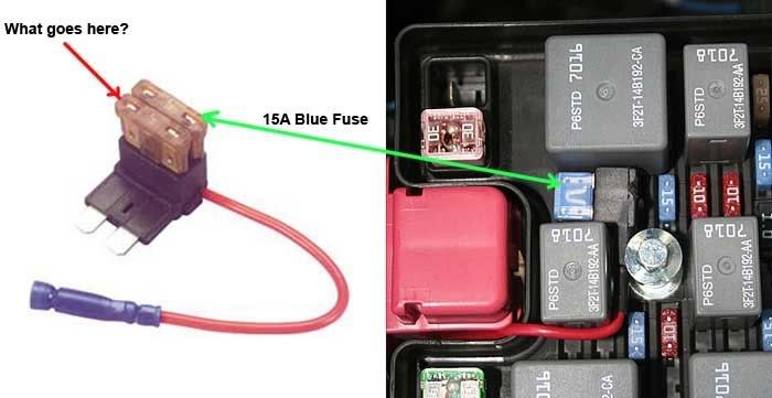
I understand that you remove that orignal 15A Blue blade fuse and but it into the top part of the Add-A-Circuit (green arrow below).
I'm not exactly sure what to put in the bottom fuse slot (red arrow below)? Do I use another 15A Blue fuse or leave it empty or put something else in there?
One more noob question about that Add-A-Circuit.
I understand that you remove that orignal 15A Blue blade fuse and but it into the top part of the Add-A-Circuit (green arrow below).
I'm not exactly sure what to put in the bottom fuse slot (red arrow below)? Do I use another 15A Blue fuse or leave it empty or put something else in there?
Thread Starter
Team Mustang Source
Joined: October 11, 2004
Posts: 711
Likes: 0
From: Surrey, BC
Other way around. The new fuse for the circuit you're adding goes into slot B, the top slot. The only thing being powered off the new circuit is the relay coil so I'm only putting a 3A fuse in there. The original fuse goes into slot A, the bottom slot
Mach 1 Member
Joined: December 5, 2004
Posts: 665
Likes: 0
Originally Posted by Redfire 05Gt
Other way around. The new fuse for the circuit you're adding goes into slot B, the top slot. The only thing being powered off the new circuit is the relay coil so I'm only putting a 3A fuse in there. The original fuse goes into slot A, the bottom slot
Legacy TMS Member
Joined: June 23, 2004
Posts: 2,147
Likes: 9
From: Pittsburgh, PA
If anyone is interested, I am selling my Meziere electric water pump. I do not get on this site that often anymore, so if you are interested send me an email (wermaner (at) hotmail dot com) I have the pump and the wiring harness.
Legacy TMS Member
Joined: November 10, 2004
Posts: 2,483
Likes: 0
ok im a bit confused with this. i have the Mezire eH2O pump and the relay kit. there are blue, black, orange, and green wires. correct me if i am wrong.
Black wires get grounded
Blue wires get soldered and heat shrunk together
orange wire with inline fuse goes to alternator output post (This is power? anywhere else to get power from?)
green wire can go to fuse 40 with the add-a-circut thingy?
please help
Black wires get grounded
Blue wires get soldered and heat shrunk together
orange wire with inline fuse goes to alternator output post (This is power? anywhere else to get power from?)
green wire can go to fuse 40 with the add-a-circut thingy?
please help
Mach 1 Member
Joined: December 5, 2004
Posts: 665
Likes: 0
Take a look at my circuit diagram I created.
That might help you.
I don't know about the colors but I think I can figure out where to connects things. You need to connect ground to the relay coil prong and connect the pump to ground too.
That might help you.
I don't know about the colors but I think I can figure out where to connects things. You need to connect ground to the relay coil prong and connect the pump to ground too.
Legacy TMS Member
Joined: November 10, 2004
Posts: 2,483
Likes: 0

Thread Starter
Team Mustang Source
Joined: October 11, 2004
Posts: 711
Likes: 0
From: Surrey, BC
You got it right. The instructions say to connect the orange wire to the alternator post but that would mean removing the alternator &/or the intake to get at it. Plus you'd have to mount the relay nearby making sure the inline fuse in the orange wire is easily accessible in case it ever pops, or run the orange wire over to the fender or wherever you mount the relay, still making sure the fuse is close to the +12v source and accessible for changing. You can also get power from the battery connection on the Power Distribution Box in the front passenger side corner of the engine compartment or directly off the battery terminal connection (again requires running the wire to the relay or mounting the relay nearby). I haven't heard of anyone mounting the relay near the alternator &/or taking power from the alternator post.
Mach 1 Member
Joined: December 5, 2004
Posts: 665
Likes: 0
Blue wires get soldered and heat shrunk together