When you click on links to various merchants on this site and make a purchase, this can result in this site earning a commission. Affiliate programs and affiliations include, but are not limited to, the eBay Partner Network.
So back in May I was talking to Eric over at JPC about the heads as I had sent them out to Rich and the cam tunnels were damaged. Rich said he would be able to fix them but suggested that going with new heads would have been the best course of action. So I got on the Horn with Steve over at Tasca and was asking him about getting replacement Boss 302 heads and he said he would look into it for me. Well turns out they were $2,860 for the pair and Ford has some very unique requirements for getting them which Steve hadn't really seen before.
The problem with the Boss 302 heads is that while they are great flowing heads right out of the box, if you want to open them up a little bit more, there isn't a whole lot of meat there to really port them so you have to be very careful in porting them and have someone who knows what they are doing. It just so happens that heads is one of Rich's passions at RGR and he enjoys doing it. That being said, the 2015 heads flow just as well as the Boss 302 heads do right out of the box and there is still room to machine them just like the heads on the 2011-2014 GT. So I had Steve work his magic on a set of heads for a 2015 and they were $1,470 including the core charge but they are bare heads meaning only valves and the springs are installed so you will have to spec out the followers, lash adjusters, and cams. So I went ahead and bought the 2015 heads from Tasca and had them dropped shipped at Rich's shop out in Indiana (He used to work out of the Chicago area, but he just recently moved) to do the Stage 2 headwork. If you are trying to make some big power and using a turbo JPC recommends going with the Stage 2 heads and if you are trying to make some big power out of your SC then Stage 3 heads are your friend generally when it comes to the RGR heads just as a point and we all know Turbo > SC when it comes to these cars and going fast.
Anyway, I digress. I got back in touch with Eric over at JPC and had told him that the heads were on their way to Rich and confirming everything on that end of the spectrum and he sent me this Invoice. It's nice to know exactly what kind of heads you are going to be getting haha.
When the heads delivered I shot a quick message to Eric on Facebook and told him that the heads arrived and he told me there that Rich was in town for his nephews graduation from Annapolis IIRC and he had dropped off a couple of shortblocks at the shop while he was there and mine was one of them so if I wanted to I could have them ship it up to me. Well since I had a couple of our guys at work heading down to the DC area I figured I would have them stop by and pick it up for me. When they got back the stories they had about going there were great. They thoroughly enjoyed their little detour on the way home that is for sure! Anyway, here it is without further ado
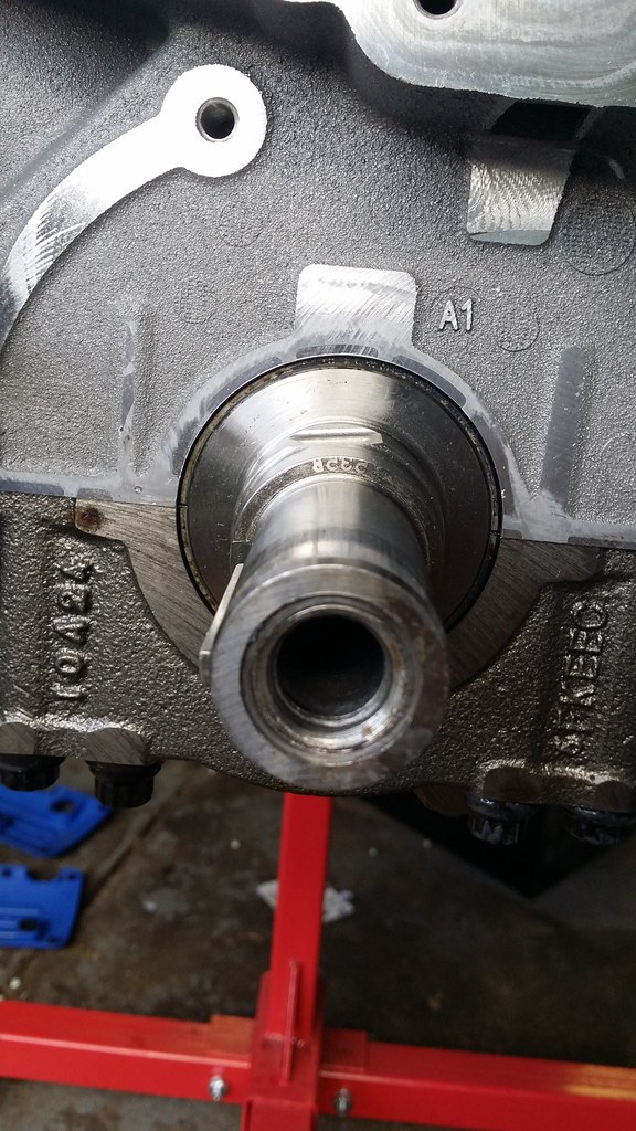
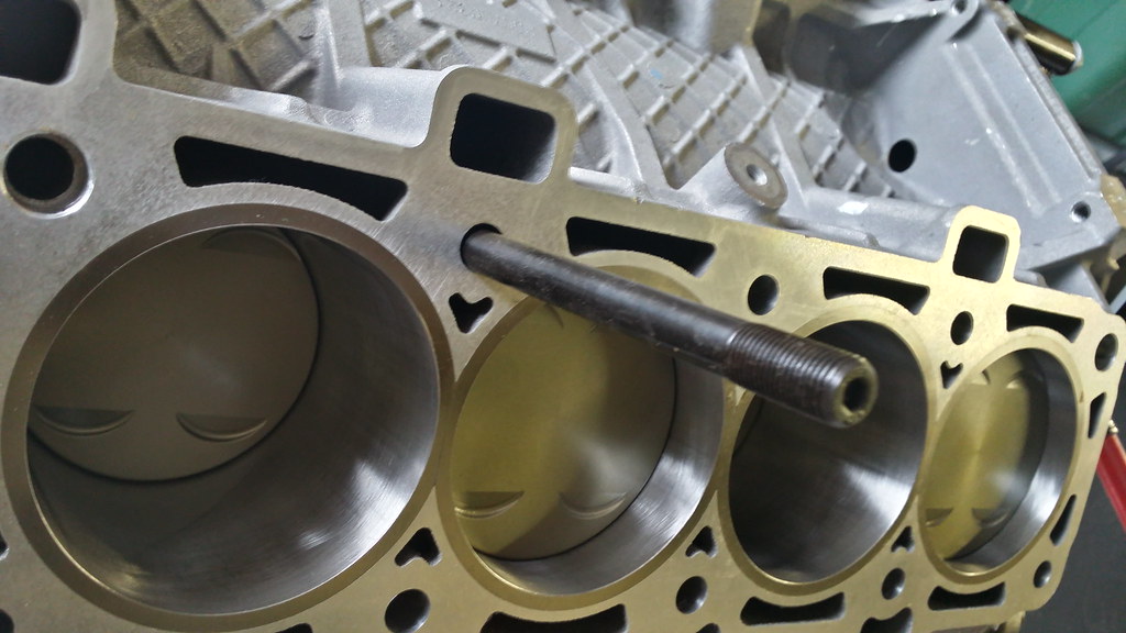
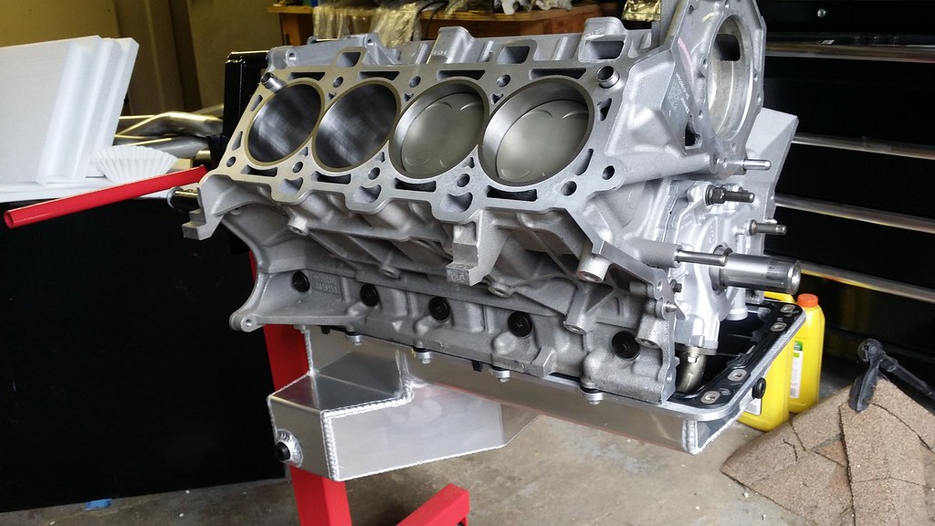
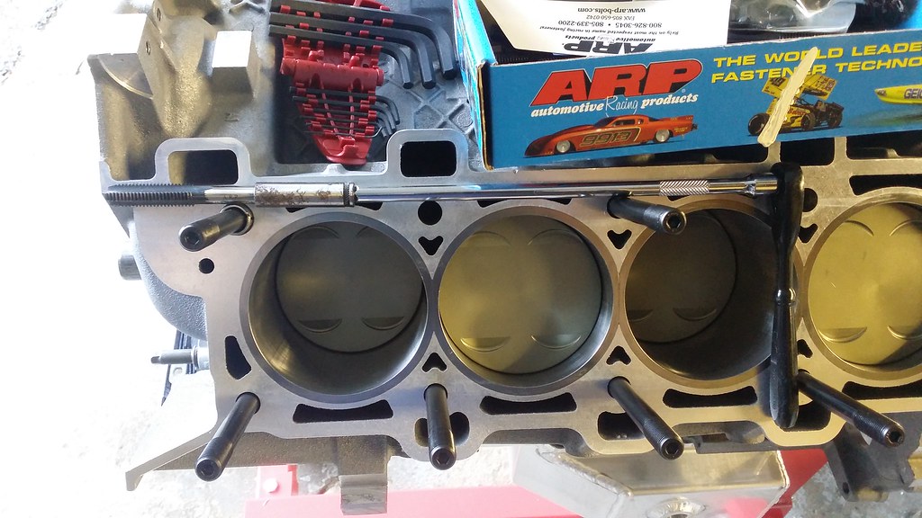
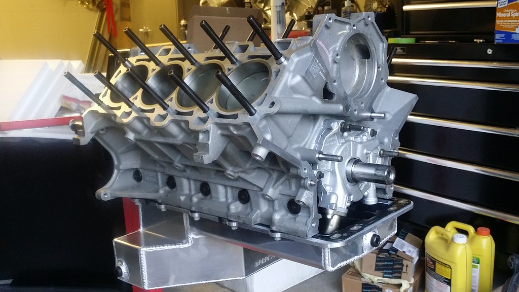
This is my 326ci Coyote engine It is a Darton Sleeved 3.700 bore block for added strength and durability along with a offset ground crank with a 3.800 stroke. If the pistons weren't specd for NA work the shortblock should be capable of holding north of 1200 and the pressures that come with it, so it is a pretty stout block for sure and Rich is one of the best modular builders in the country so I couldn't really ask for a whole lot more out of this engine except for **** near 600HP to the wheels.
Well I thought I had a picture of the heads when they came in from RGR but I can't find it. Anyway, they are a work of art, both intake and exhaust ports look amazing. I finally got the custom grind cams from Rich as well in August after the person that grinds the cams at Comp for Rich was out on vacation.
When it comes to the cams in these cars on a N/A engine, the Coyote loves to have a large duration cam in it while keeping the lift at a relatively stock level. I won't disclose the cam grinds as those belong to Rich and they are a closely guarded secret as a lot of effort and time go into developing the specs. But here it is in all of its glory bolted up to the engine stand.
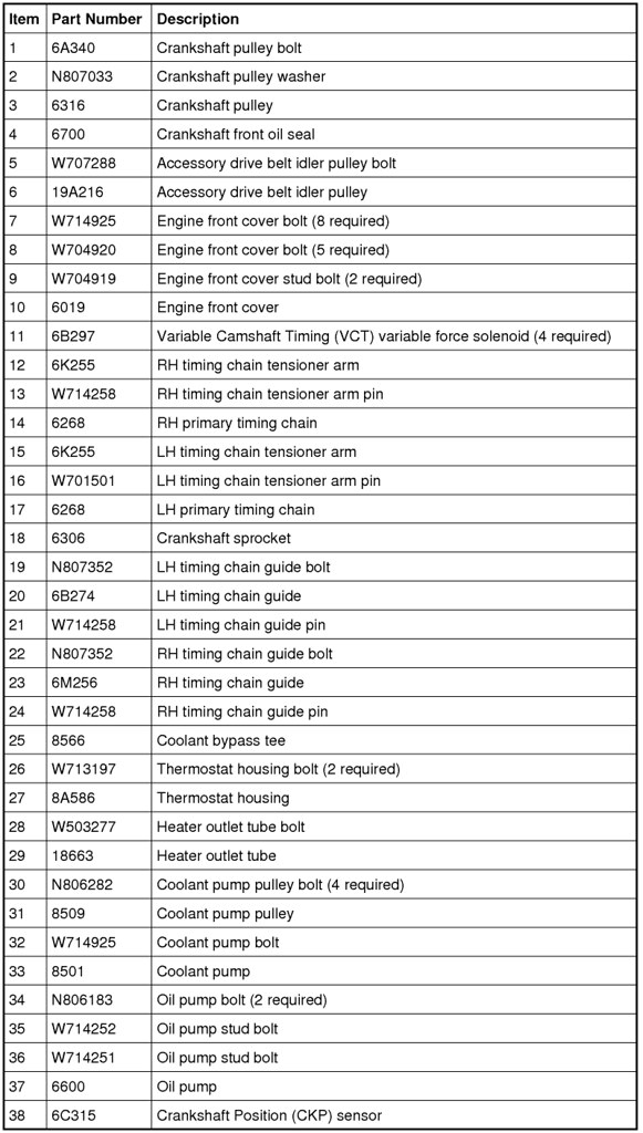
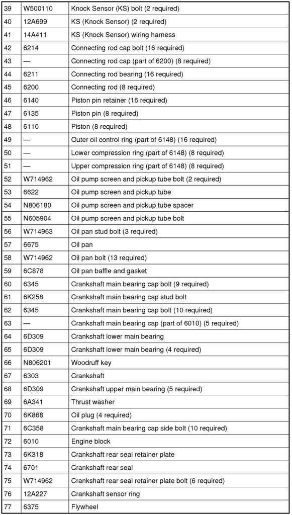
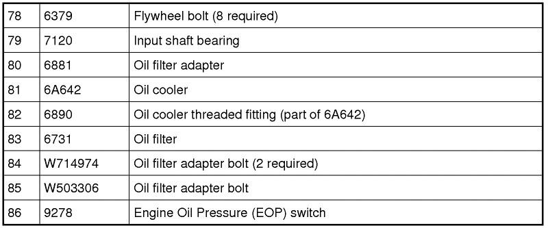
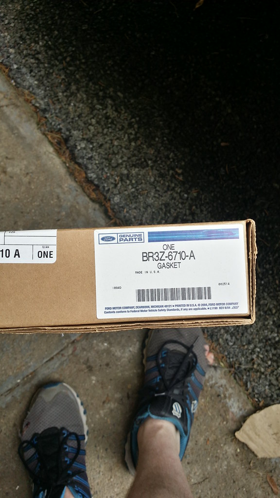
I just want to say that my Boss was built in December of 2010 so the part numbers may vary from what you might have. The best thing to always do is give your VIN# to your favorite Ford Store (in my case Steve@Tasca) and let them look up the parts for you.
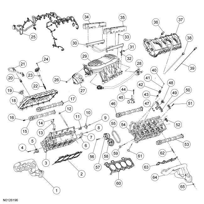
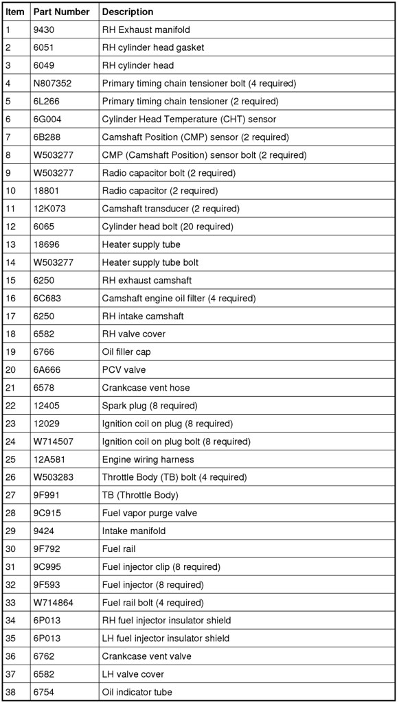
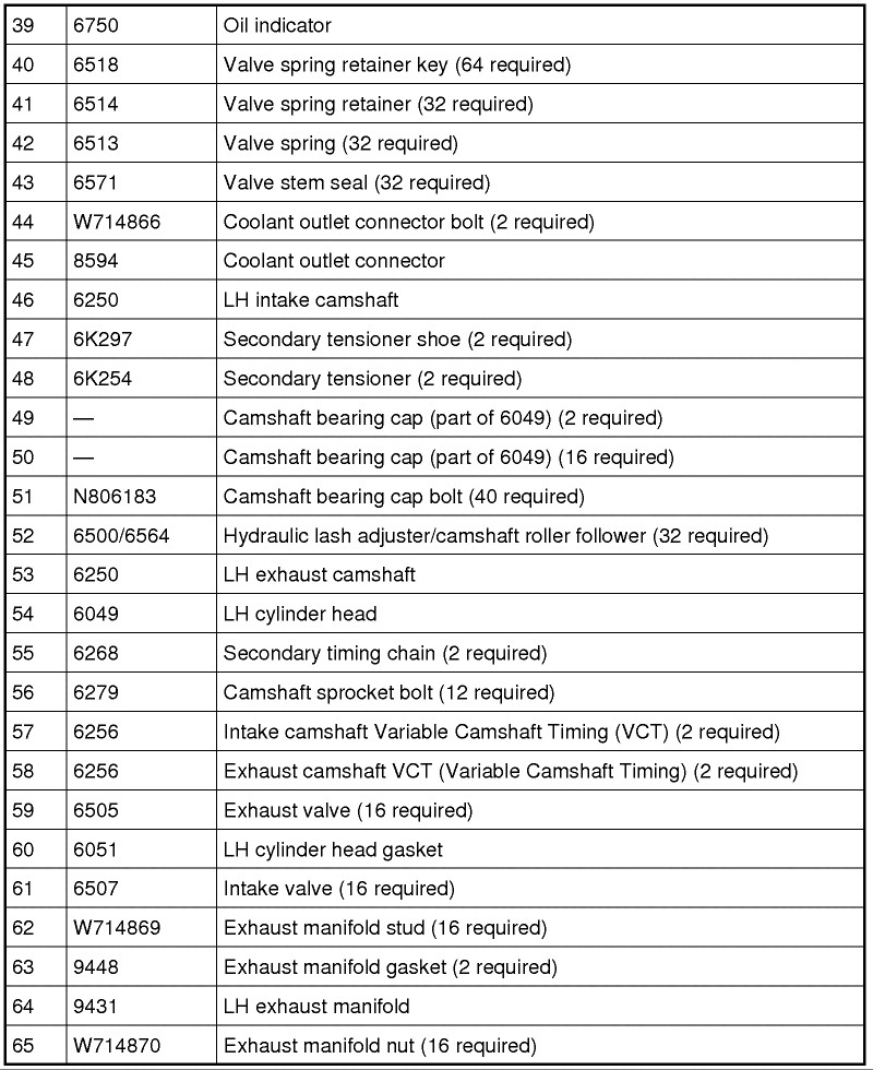
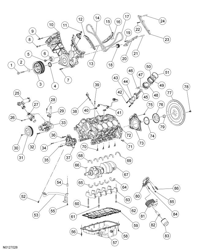
Onto the good ****! For anyone interested I have these exploded view of the parts list for the Boss and GT motors (this one is the Boss motor but they mostly share the same components, just different parts and subsequently, part numbers) if you want the GT version, let me know and I can get that to you.
How much more flow are you getting with the new heads Sean? Percentage wise?
That is a very good but hard question for me to answer. The reason why is because there is no one that I know who has published the flow numbers on the Boss 302 heads and I have looked pretty extensively. The only thing I was able to find was that the Boss heads flow a certain percentage higher than GT heads but they never elaborate on that. Not to mention with the 2015 heads I don't believe anyone has put them on a flow bench yet, but they should be pretty close to the flow numbers on the Boss 302 heads. Considering that all of the flow numbers are calculated using the stock bore which is 3.630 and my bore is 3.700 it is hard to compare them.
Anyway, a while back I did make these graphs regarding the flow numbers between the stock heads and RGR Stage 2 heads which should give me a close look at the differences in flow numbers.
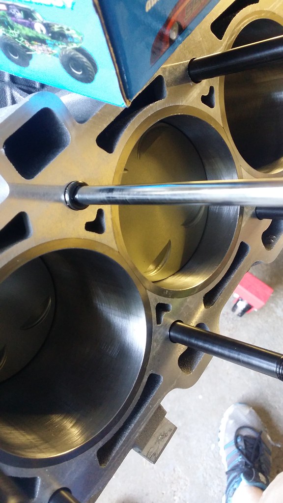
I went on ahead and grabbed my oil pump. I looked at the crankshaft to locate the orientation of the two flat parts on my crankshaft. In the picture you can see that the flat part is at an 11:58 position, so what you do is you rotate the gears in the oil pump so that the subsequent marks align with the flat pieces on the crankshaft.
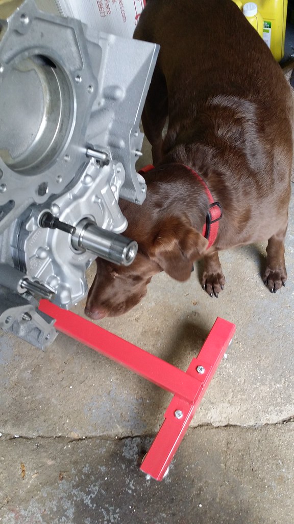
From there all you do is slide the oil pump flat up against the block and you can put your oil pump bolts and studs into place. I even had my helper with me today!
Here is the oil pump placed onto the block but at the same time I didn't have a torque wrench that could handle the required torque specs of the oil pump bolts and studs. So, I had to go out and buy one. Anyway, the torque specs and whatnot are below
From there all you do is slide the oil pump flat up against the block and you can put your oil pump bolts and studs into place. I even had my helper with me today!
LOL
That's awesome bro. Dogs make the best helpers. Sometimes. lol
Awesome thread Sean. Keep it going.
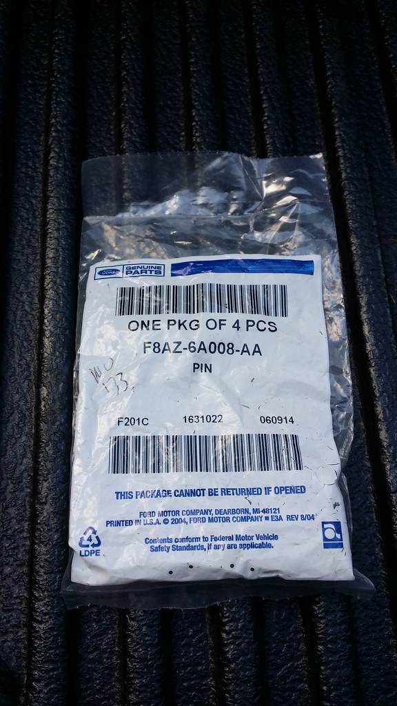
After I put the oil pump on and realized I couldn't torque the bolts down I figured I would go ahead and start putting the studs in so I can at least get the heads on as well as the cam covers to prevent any debris from falling into the engine. At least I can get those in without any issue. I grabbed the dowel pins for the heads (you should always get news ones for your build, they were like 4 bucks) and tapped them into place with my hammer. Once they reach the bottom they make a different sound when you hit them so you will know they are in there.
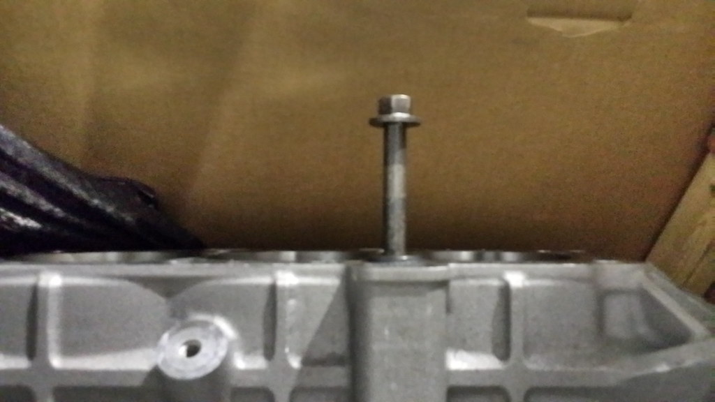
I ordered the block back in January and in the subsequent 5 months JPC and myself had forgotten if I actually had a 2013 block like the invoice stated or if that was just a place holder signifying a used block was on the invoice, so I talked to Eric at JPC about head bolt options and while he agreed that I would probably be fine with the TTY bolts, it never hurts to go with the ARP head studs. I agreed with that sentiment but my wallet was none too happy about hearing that haha. So I went and grabbed a head bolt from the Boss and proceeded to screw it into the block to see if it would go in. Sure enough it screwed in hand tight without issue. Well I guess that solves the debate about what year block I have!
Or so I thought �..
I went to go put the ARP studs in and they drop right to the bottom of the hole without touching a single thread �..
I can�t win, Uncle Murphy has struck again. Anything that could have gone wrong went wrong here and it was just the beginning of the day haha.
Parts Used
Dowel pins - FA8Z-6AA008-AA
11-12 ARP Head Studs - 256-4702
13-14 ARP Head Studs - 256-4301
Well after that and the not being able to torque down the oil pump bolts I was sort of bummed, but I remember what Matt D said in his Coyote swap thread:
Originally Posted by Matt D
Let me start off by saying... when doing a big or decent size build the main key (other then running out of money) is to not loose motivation!
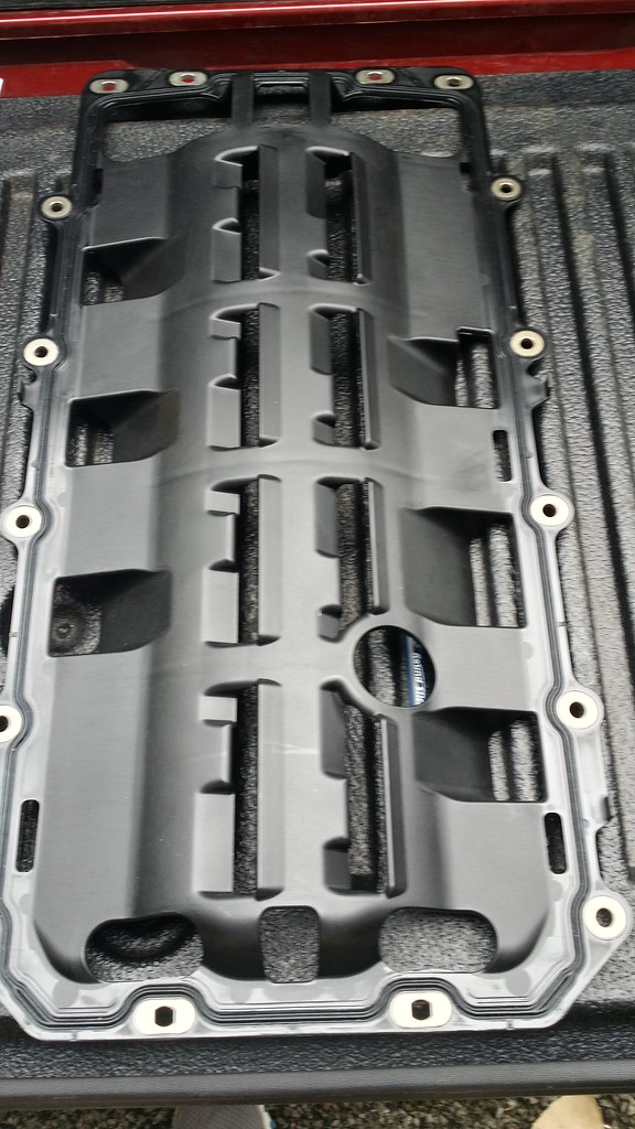
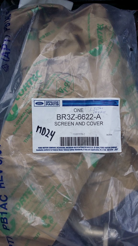
So, I ran into my bedroom and stared at Mt. Car parts and grabbed the 3 boxes at the bottom of the pile. I figured I shouldn�t lose motivation so let me see this beautiful thing on the motor. Too bad you are never going to see it once it is in. I dug through my parts bin and pulled out the baggie labeled Oil p/u tube and spacer and I threw those in �my parts washer� tubs and cleaned them off with some dawn, clean water and coffee filters since they are cheap and lint free. I went ahead and put the pickup tube spacer on, and then I grabbed my oil pan gasket/windage tray.
I took a look at it along with most every part I have put on to ensure there was no dust or debris that could get into the motor and cause damage and would you look at that � dust and junk!
One of the many things I distinctly remember from tmcolegr�s build thread on S197 forum is that cleanliness is very important as well as check all your parts even new ones so I am being careful with the items I put on there. I wiped off the dirt and lubricated the gasket on both sides of the windage tray. Remember, the convex side faces up (just as it is in the picture. I then proceeded to grab my oil pump pick up tube and lubricated the gasket on that as well and put it into place.
I didn�t torque any of the pickup tube bolts or the spacer bolt as those are in/lbs. as well. I then put the pi�ce de r�sistance on and turned the shortblock around and looked at it. It is starting to look like a real engine again!!!! Motivation returned!
VERY IMPORTANT!!!!
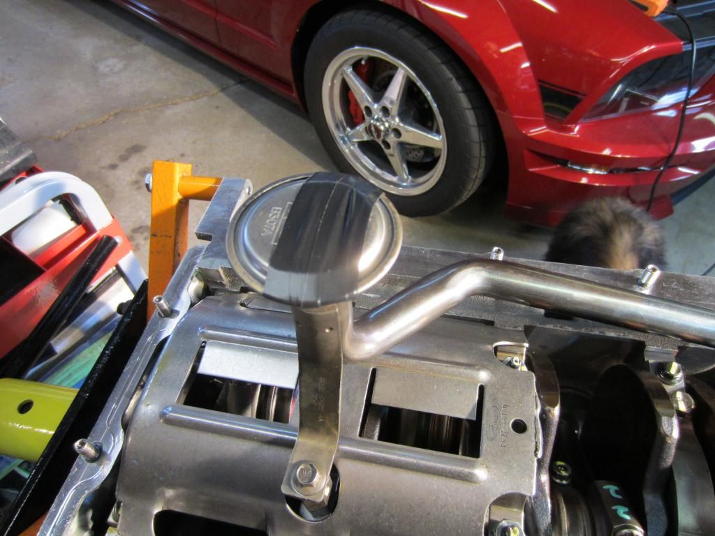
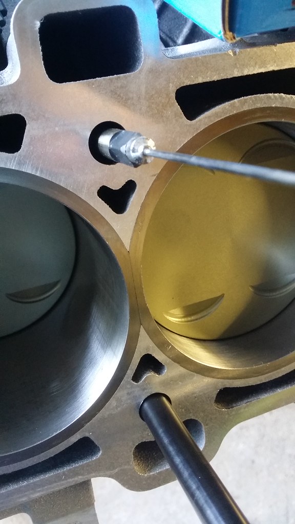
Anyway, after looking at everything and admiring the beautiful oil pan I had to take it off to check oil to pan clearance. This is very important and regardless if you are using the same exact parts that you just took off you should always check the clearance as if the clearance is too tight then you can restrict oil flow to the oil pump and subsequently to the rest of the motor which will eventually lead to oil starvation. Moroso recommends .250" - .500" of space as it is using the stock pickup tube. I never took pictures during this stage but I will highlight the meathod that I used to check the clearance using tmcolegr's post in his thread. This is on a 3V, but the process is the same regardless.
Originally Posted by tmcolegr
The procedure to determine the oil pan to oil pump pickup tube clearance is very easy to perform - refer to following pictures.
Measure the oil pan rail to sump dimension
Measure the thickness of the oil pan gasket. For those of you using multiple gaskets with a windage tray or crankshaft scraper, measure all those as well and add up that total thickness.
Measure the height of the oil pump pickup tube to pan rail of the block
Now calculate the oil pan to oil pump pickup tube clearance. Oil pan depth + oil pan gasket(s) thickness - pickup tube height = oil pan to oil pump pickup tube clearance.
After checking oil to pan clearance I believe I was at .365" which is within spec for Moroso so I know that I am good to go on that aspect.
Bummer about not getting the heads on. Hopefully soon enough.
But, looks killer with the oil pan on. That oil pan is a killer piece. Look at those welds! NICE!
Great build, keep the progress reports and pictures coming!
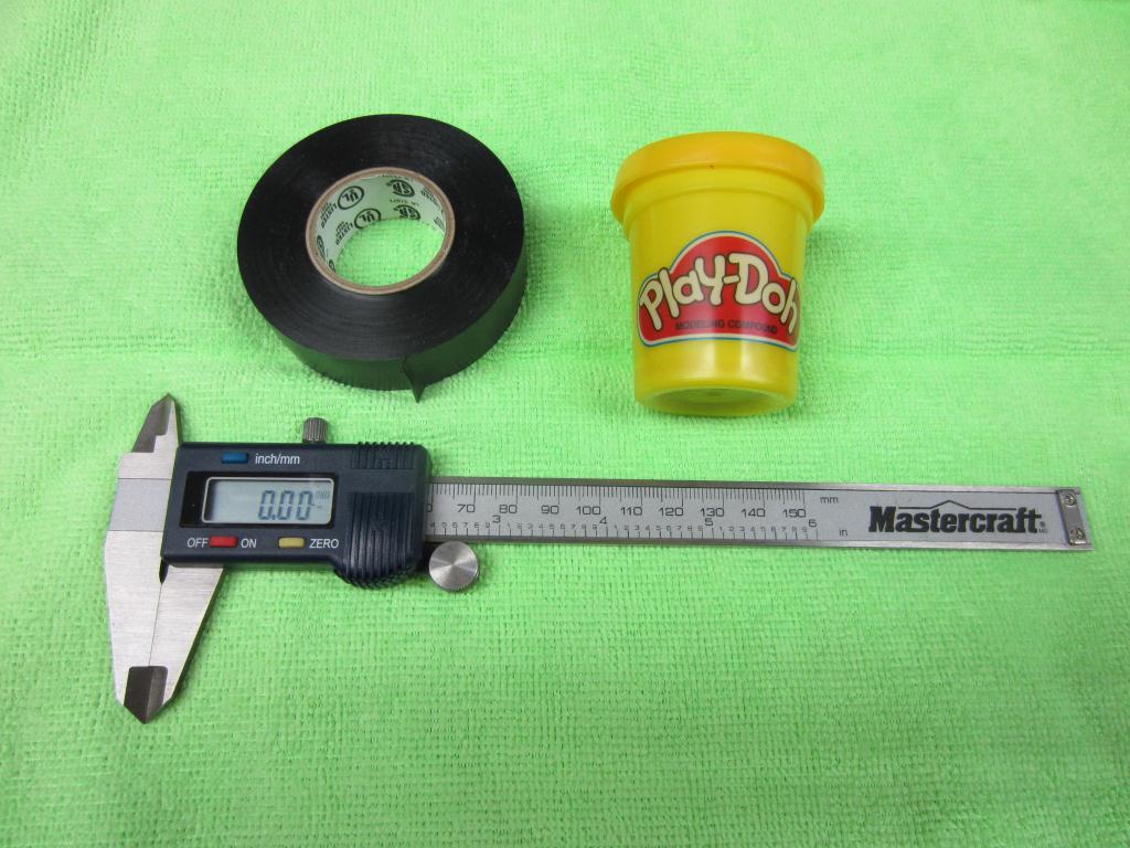
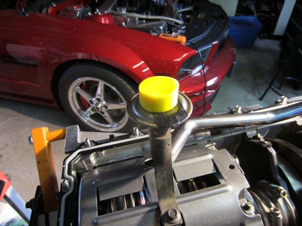
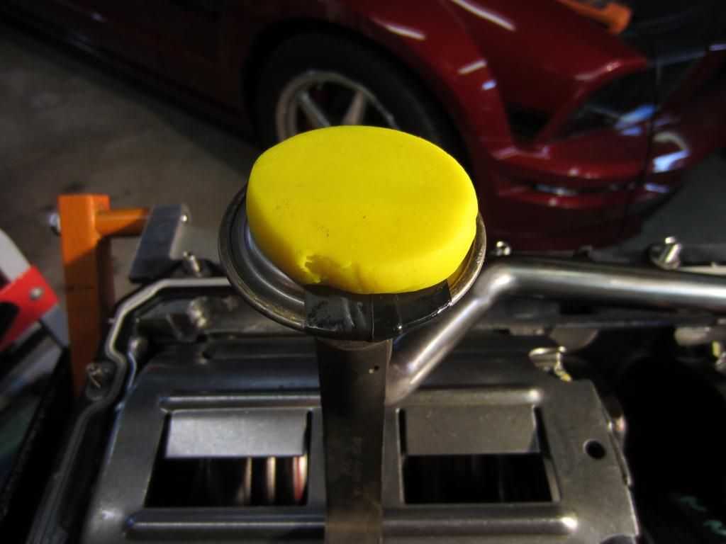
BTW there is a "funner" way to check oil pickup clearance, it is called the Play-Doh method as pictured here.
Torque the pan with gasket down to specs.
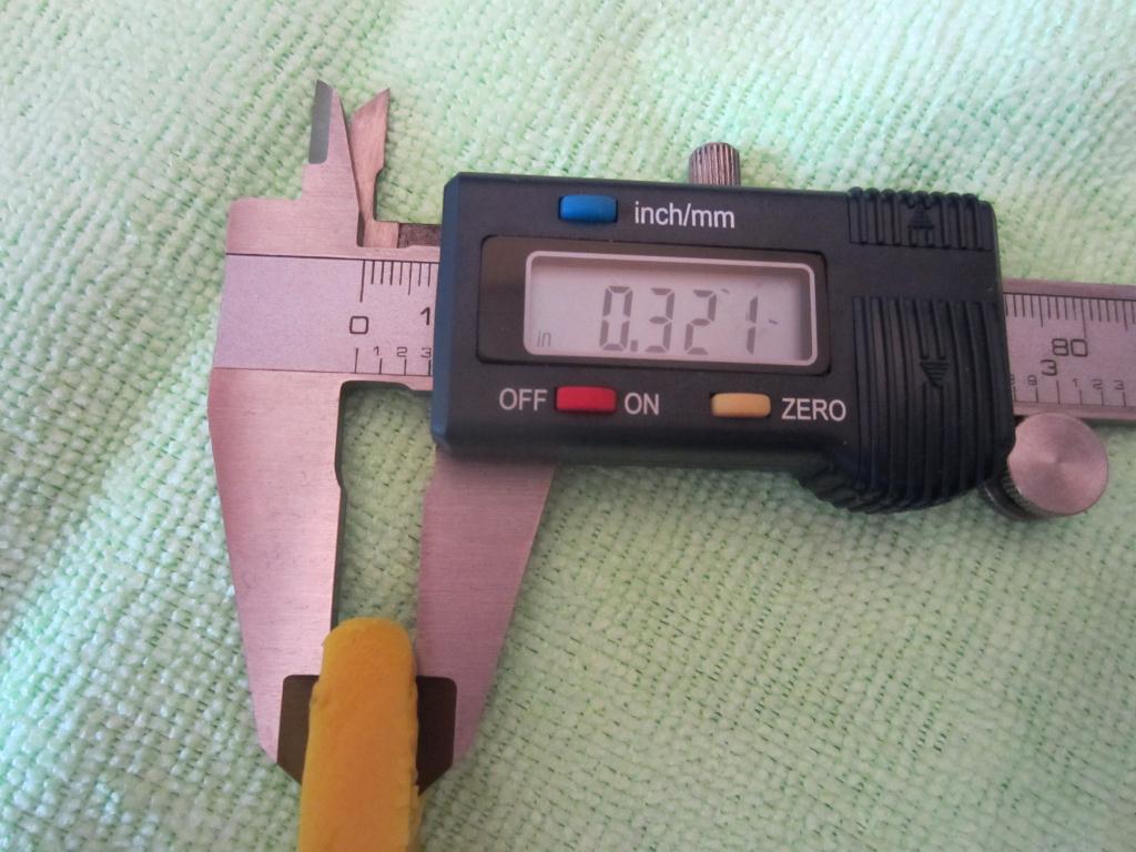
Measure thinnest cross section.
One must of course remember to remove the electrical tape!
I like that way better! Had I had play-doh then I would have prefered that way, IMO that is much better and easier. I did get some play-doh to check PTV clearance but I didn't get to use it
Well, I got the head studs in. I ended up having to chase the threads in 2 holes (oddly enough right next to each other) and the studs threaded into place without issue. The issue I ran into was that the Tap that ARP sells you is 3.5� long and the threads start 3.4 inches into the block. Thankfully, by the grace of god the 5/16th deep socket was the perfect size to fit the end of the tap as well as the hole.
My contraption
I **** near **** my pants trying to decide should I continue at this point and potentially **** myself or stop. I live dangerously and kept going, thankfully one more turn and it reached the bottom.
Then I can pull it out with my magnetic extension.
Now, all the studs are in their place and ready for the heads. I�m not too certain how important this is but after screwing the studs by hand, as per ARP instructions, into the holes and touching the bottom I measured them and they were all within 2 or 3 thousands of an inch (3.556� was a common number) minus 1 which was 3.49X".
In the words of the infamous SDWheeler ..... Oooo Studly!!
Parts Used
Thread Chaser Extension
ARP M12x1.75 Thread cleaning tool � Part # 912-0008
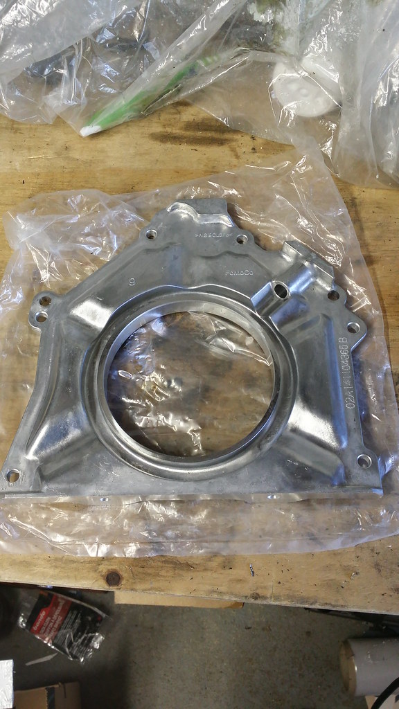
It was at this point that I realized that I had forgotten to put the rear main seal plate on since I didn't have the installation tool for the seal, nor could I find the old seal or a piece of PCV big enough to install it so I guess I never really put it in my mind that before I remove the engine from the crate to put the seal on. This should be the first thing you do, but I forgot. Anyway, no harm no foul as I hadn't put anything on the engine really.
I just want to give a HUGE thank you and a shout out to Tad @ Freedom Racing. Some of you know Tad from S197forum or and others may not. Freedom Racing has all sorts of OEM tools that you can buy or rent for a reasonable price and their service is second to none. Every time I get in touch with Tad, it is unfortunately on a weekend and usually within 15 minutes or so I have a PM back from him. Well Saturday night I went ahead and asked him a bunch of questions about certain tools and whatnot and he told me that he would run down to the shop tomorrow (on Sunday) and get me the answers. Sunday afternoon I had all the info that I needed with a special quote and everything all ready. Tad is a hell of a guy and I love Freedom Racing, everything always goes so smooth and I have never had any issues with them.
Anyway, back to the fun
Seeing as I now have what I need to put in the retainer plate and the rear main seal I figured now was the time to get things done. So, off comes the oil pan, pickup tube and windage tray so I can put in the retainer plate.
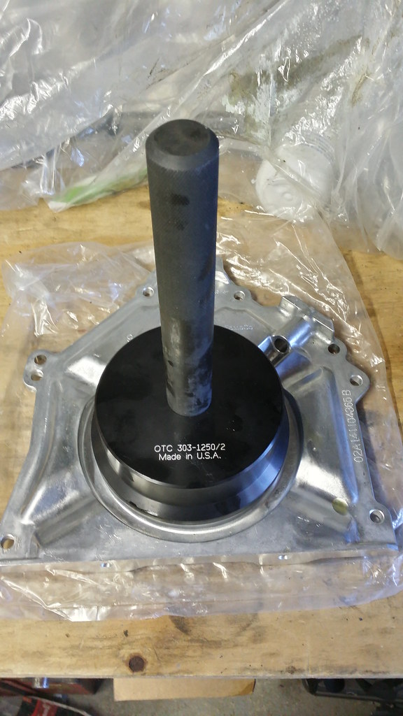
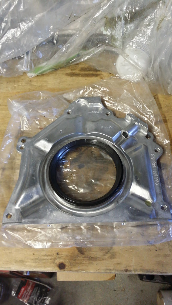
I open the box and pull out the necessary tools and get to work. Seeing as how I have never done this before (as pretty much everything with the build) I figured I would do a little step to step for those who have never done it before. With the retainer plate on my bench I cleaned the area where the rear main seal goes and lubricated the rear main seal along with the hole where it fits into and just positioned the seal on top of it with both indication marks and the 12 and 6 position.
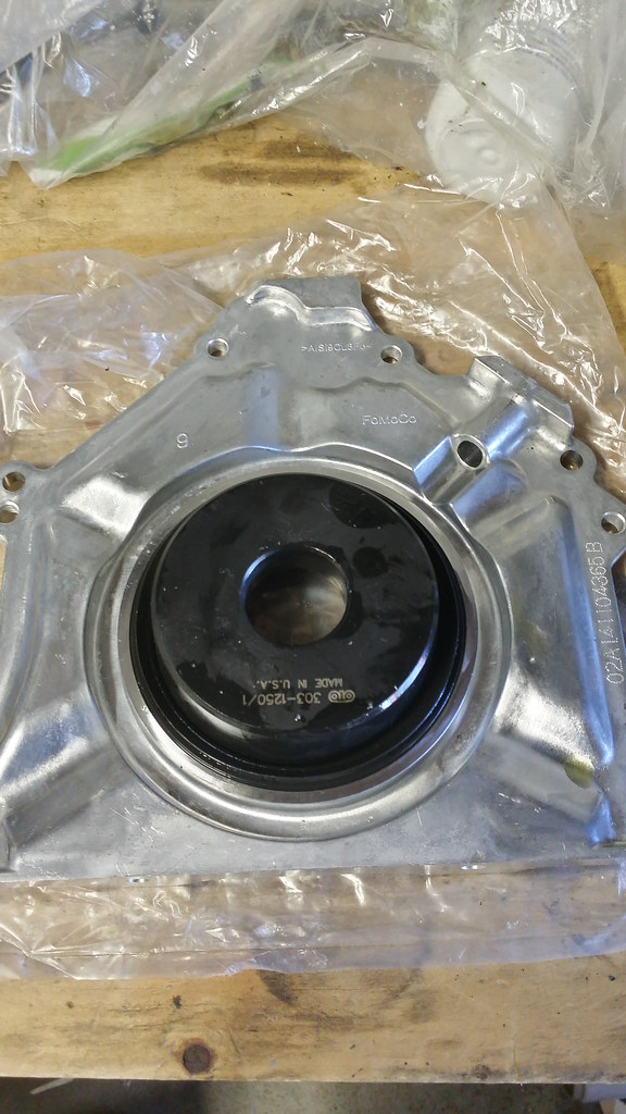
I then put the tool onto the rear main seal
I then grabbed my BFH (Big ****ing hammer) and hit the shaft until the seal top of the seal laid flush with retainer plate as the OEM one is.
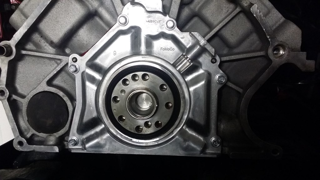
I then took the engine off of the stand and put it back in it's crate on the tailgate of my pickup and went to go ahead and put the seal on. Using Permatex Anerobic Gasket Maker I put a bead of this on the motor. According to the service manual, you put the bead on the motor, not on the retainer plate itself. I don't have a picture of this as it was night and I just wanted to get inside and shut it down for the night but the rear main seal is on.
Note: When putting this on, use a continuos bead of gasket maker and do not move the plate sideways when placing the plate on or as per the manual, you stand a greater chance at having the gasket leak. That would be a giant pain in the *** considering the location of the plate.
Parts list
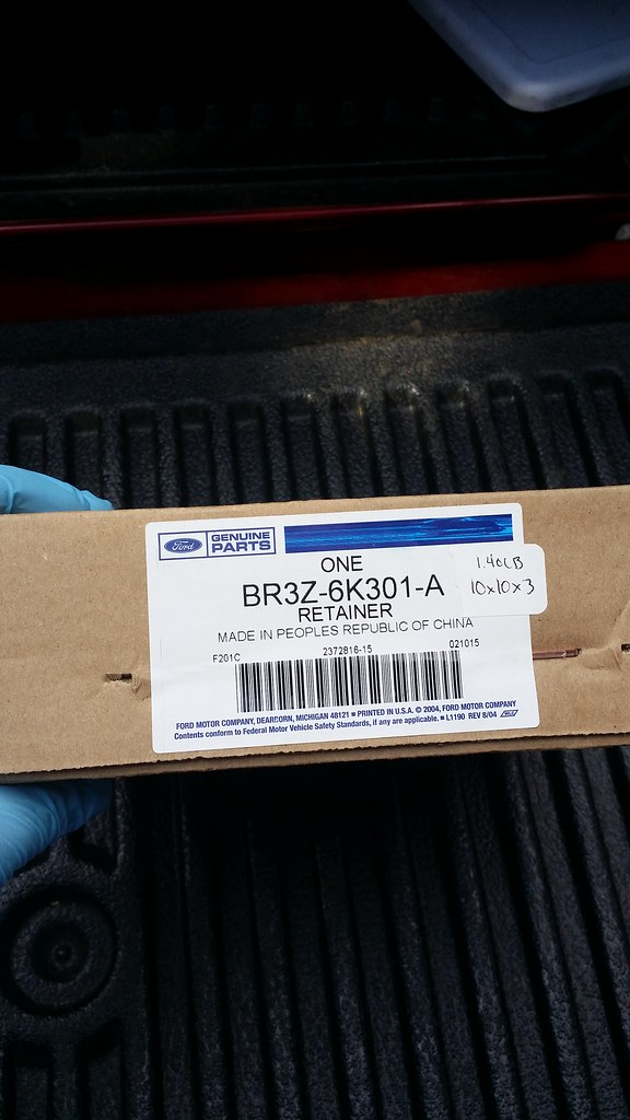
Retainer Plate - BR3Z-6K301-A
Retainer Plate Bolts - W714962-SXXXXXX (I don't have the last part of the Part number for the bolts.
At this point, I had nothing that I could really do as I was waiting on the billet crank sprocket from Tim Eichhorn over at MPR Engines down in Florida so I made this while I was waiting.
Waiting on car parts like .....
I always have felt that these lower crank sprockets were another safe part to buy. I have seen a few of them break over time on FI cars and people who run their cars hard as just like the oil pump gears, these are made of powdered metal so they can fracture and snap as well. When this happen the results can be disastrous, you can bend valves, destroy followers which can damage your cams, springs can break and you can score your crankshaft. For the $250 that I paid for mine it was such a worthwhile investment. There is no sense building a motor for thousands of dollars only to have such an important part fail on you and destroy the engine. As I said previously I bought mine from MPR Engines in Florida and Tim Eichhorn does nothing but amazing quality work and is one of the best modular builders in the country. I would expect nothing short of excellence with anything that comes out of his shop and that is what I got when they arrived. If you are looking to go ahead and grab some MPR doesn't have a website so you are going to have to call them and order them or you can go ahead and jump on their facebook page here and send them a message about them. They are wicked fast with their messages so don't hesitate to send them a message.
Within a few days Tim let me know that he had them in stock and shipped them out. My expectations went above and beyond! This piece right here is a work of art and very hard to manufacture correctly! The OEM one is on the right while the MPR Billet Steel version is on the left.
I also want to go ahead and let you know that when talking with Eric over at JPC about some other things for my build he had noticed that I had my oil pan on the engine already and told me to take that off despite what the service manual says. The thing is that with the oil pan on the engine you can't properly ensure that the balancer is on correctly and seated the right way. Just a little more advice that I found in the process of my build.


 It is a Darton Sleeved 3.700 bore block for added strength and durability along with a offset ground crank with a 3.800 stroke. If the pistons weren't specd for NA work the shortblock should be capable of holding north of 1200 and the pressures that come with it, so it is a pretty stout block for sure and Rich is one of the best modular builders in the country so I couldn't really ask for a whole lot more out of this engine except for **** near 600HP to the wheels.