When you click on links to various merchants on this site and make a purchase, this can result in this site earning a commission. Affiliate programs and affiliations include, but are not limited to, the eBay Partner Network.
I'm keeping track of the good vendors you've dealt with, never know when I'll need some good help.
In all honesty I sent a message to Tim on a weekend and he got back to me within a few minutes and even after hours I had a question and he got back to me. The same with his son. When I was looking for the heavy duty secondary chains Tim was in PA I believe with Evolution Performance and Tyler was running the show and as soon as he got them I knew about it and they shipped the same day. Even Eric over at JPC I would message him on facebook and the guy would answer me without issues and a few minutes. He is slow answering emails or sometimes he doesn't answer them but if you call him he is on the spot. Aaron is better with emails and PM's than Eric but they are stupid fast at getting back to you considering how busy they always are.
Originally Posted by Stage_3
Killer thread.
Yeah,...the oil pump gears are some of the first things to go on the S550 cars that are boosted as well. Great upgrade.
For sure, I think I spent a total of $500 with the OPG's and the crank sprocket and if they save my $15k+ motor than it was well worth the money.
Well right before the engine came in I went a little Ford Racing Happy and bought a boat load of stuff. Some of these parts just came out so Steve didn't even have the Tasca price on them just yet which means I was one of the first to get them I guess haha. Anyway, my pile of goodies
Coyote Camshaft Drive kit - M-6004-A504 - Includes new Primary and Secondary phasers, Boss 302 Primary tensioners, secondary tensioners, primary chains, secondary chains, oil pump bolts, tensioner pins, tensioner arms, camshaft filters, crank sprocket, tensioner hardware, and camshaft bolts
Coyote Engine Harness kit - M-12508-M50 - Supposedly with this kit there is no rewiring needed for switching to the Cobra Jet Intakes and throttle bodies. We will see how well that claim is. That being said you need the following VCT actuators for this kit.
2/27/12 or newer VCT solenoids - BR3Z-6M280-D
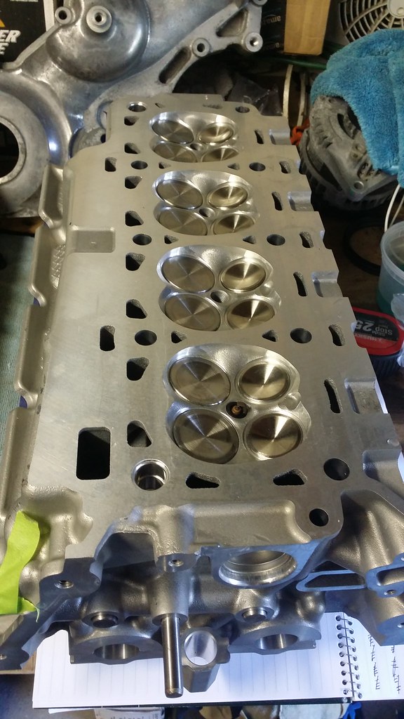
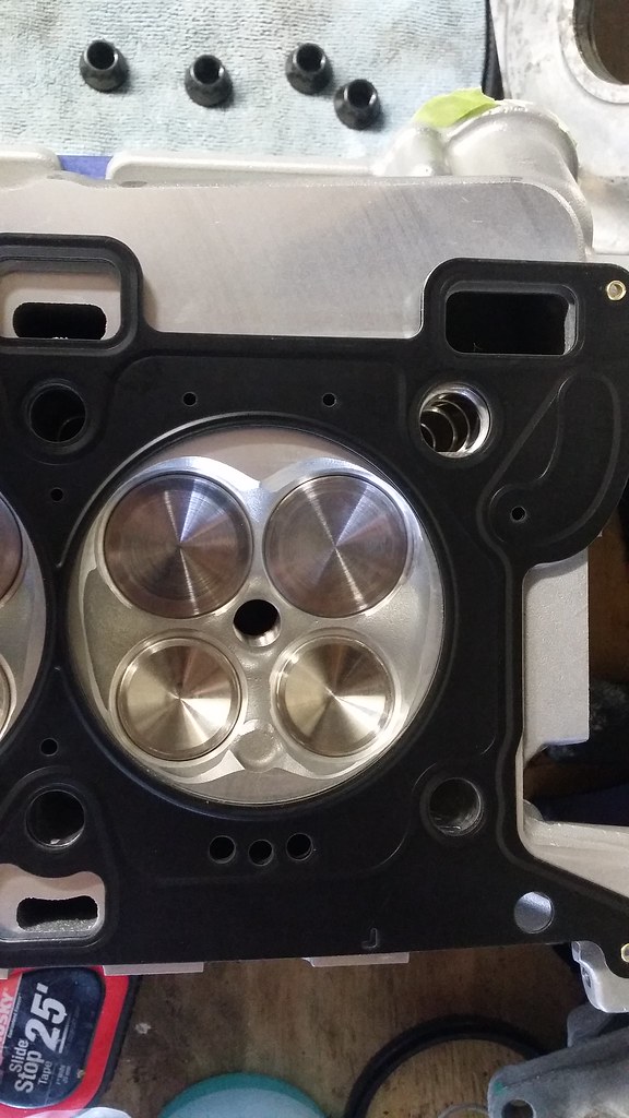
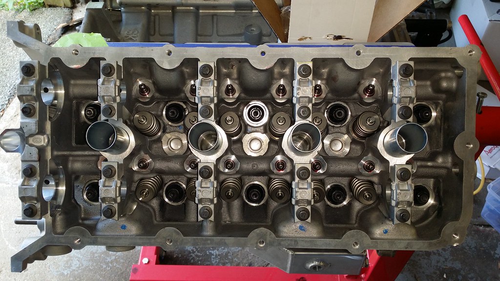
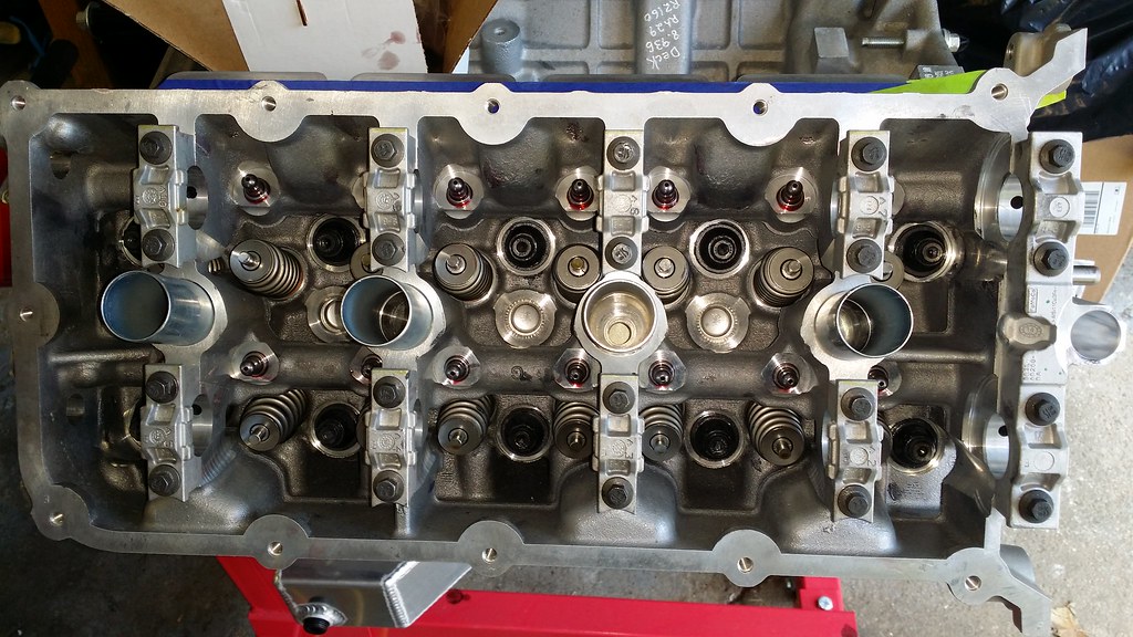
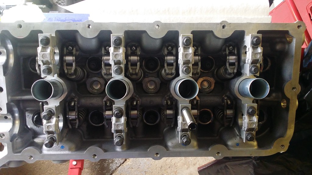
The 2015 heads come bare with just valves, valve springs, and keepers so I also needed to get some roller followers along with the lash adjusters. I had the heads shipped to me and got them all ready to be put in. I have to say they are a work of art IMO. Trick Flow Valve Springs, RGR bronze valve guides Ferrea oversized valves, and a nice port work to the intake and exhaust ports along with some bowl work and a whole slew of things I am probably forgetting.
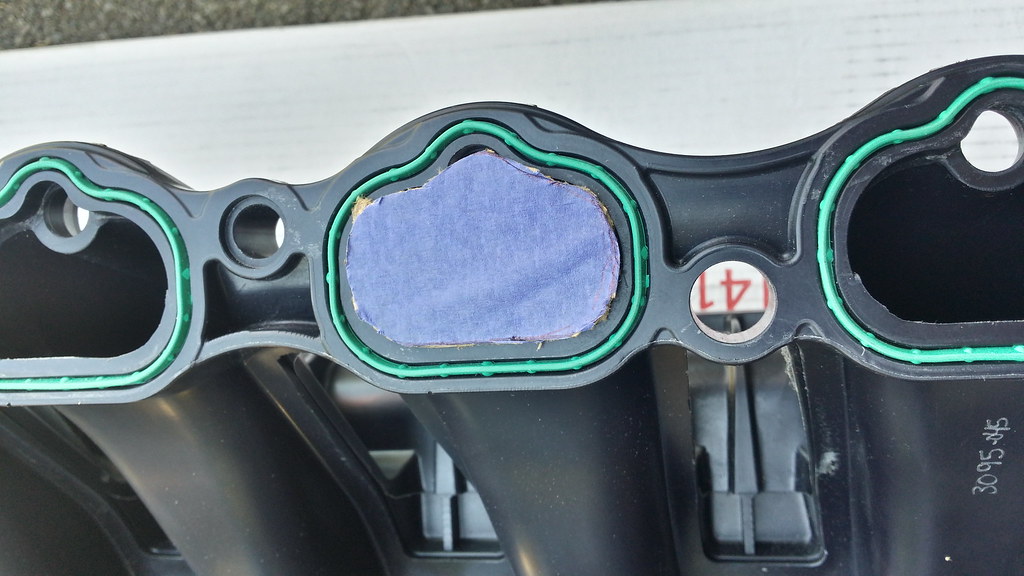
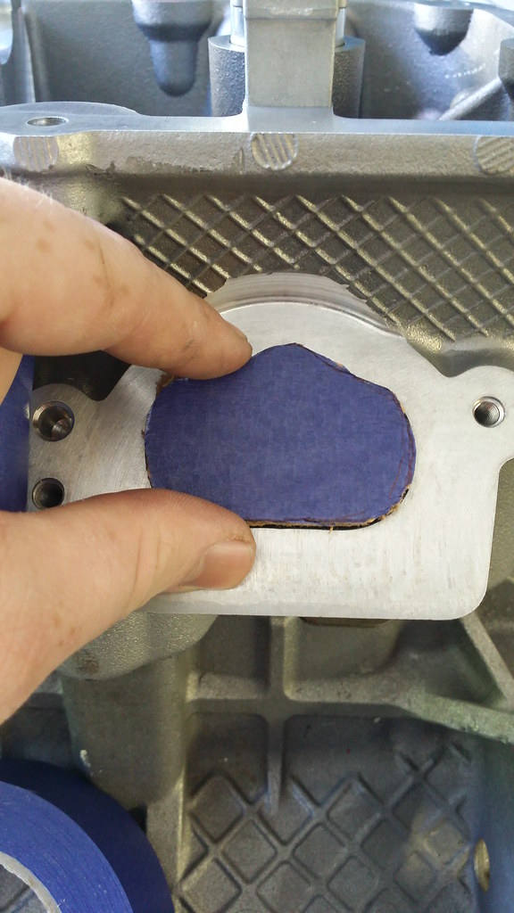
That being said, there have been people noticing that their Cobra jet Intake Manifolds intake runners were much larger in size than the intake ports are on the heads. That will cause a little bit of loss in power than if the ports were matched in size.So I took some painters tape and grabbed my x-acto knife and traced the intake ports on the manifold and transferred that over to some cardboard. Well would you look at that
Perfect fit! Don't mind me holding the piece on the head, if I had let it go, it would have fallen down the intake port and I really didn't want that to happen.
From this point I wanted to calculate my compression ratio so I needed to know the combustion chamber volume so I grabbed the tools needed (sorry no pictures of this). You need your spark plug as the spark plug takes up a specific volume in the combustion chamber, a piece of plexiglass with a hole cut in the center, some sort of way to measure the liquid going into the Combustion chamber (a syringe works as it has a marked volume on it), some vaseline and some water. The first thing that I did was to level the head so I grabbed a bunch of coffee filters I use to clean parts and folded them up until I got the heads nice and level. What you are doing is taking your water and filling up the combustion chamber with a specified CC's of water. The factory size is 54.5cc's so when you get to this point you take some vaseline and put it around the combustion chamber to seal the chamber off, now take your piece of plexiglass and put it over the combustion chamber. From there you can continue putting water in the combustion chamber. When you start to get to the top of the piece of plexiglass, you stop. Subtract what you have left in the syringe from the volume of the syringe and add up how many times you added water into the combustion chamber ie. if you have a 10ml syringe (although mine was .5ml URGH) and you filled it 5 times and you have 4 ml's of water left in the syringe you have a combustion chamber size of 56 cc's.
Now that I know this I can go ahead and calculate my compression ratio. While there are calculators out there that will do the math for me, I like to do this sort of stuff so I sat down with a pad and pencil and went about calculating the compression ratio myself. While there are a certain number of ways to calculate your compression ratio, I decided use a technique called slicing pi as it seemed the simplest and easiest way to do this.
Bare with me as we are about to embark on a treacherous journey into the world of ...... MATH
When calculating your compression ratio there are 5 variables that we are going to need to find and we are going to need to solve for. In looking at the ways to find your compression ratio I saw this video and it stood out to me as the most detailed and concise way to find your compression ratio. Beware though, it is 20 minutes long but it is very thorough in the explanation. I have also found a love for Jafromobile and his videos now because of this.
Anyway, snap back to reality and math!! Ok, so the variables that we need to solve are as follows:
V1 = Swept volume - Here you are calculating the engine volume based on the bore and stroke of the cylinder.
V2 = Gasket volume
V3 = Piston to deck volume - Here you are calculating the distance between the piston at top dead center and the deck
V4 = Piston volume
V5 = Head combustion chamber volume
Getting my measurements
I know what my bore is based on the proposed measurements brought forth by RGR & JPC. I don't have a dial bore gauge to calculate my actual bore but when I measured it with my dial caliper at the top (I know this is entirely wrong and un scientific but I didn't have the right tools available to me at the time) it measured out 5 times to an average of 3.699 in, so I am confident in their measurements on stroke as well which I know is 3.800.
In order to find the crushed gasket thickness of the gasket I am using I contacted Cometic and asked them for the crushed measurement and they said that it will be .040 as listed on the packaging and all of the crushed thickness' will be listed on the gaskets so my gaskets crushed thickness is .040.
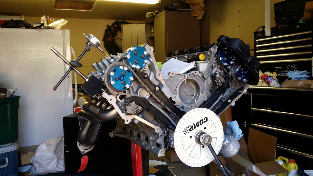
In order to measure my PTD clearance I had to find TDC on the number 1 piston. Out came my dial indicator and stand that I got with the Comp Coyote Camshaft Degree Kit. Unfortunately, I didn't have anyway to securely fasten it to the deck so I had to hold it steady by hand. Not an easy task to do when you are trying to rotate the engine at the same time. Anyway, it ended up taking me about an hour to find TDC and then I spent another 45 minutes making sure that it was true TDC which ended up with me double checking my measurements 8 times. So, I set TDC and grabbed my smallest feeler gauge and went all the way around the entire piston and couldn't get it threw so I knew the gap was at least .004" I checked with Eric over at JPC about this and he said that Rich makes sure he zero decked the engine. Considering I couldn't get a .005 feeler gauge in there nor could I see daylight between th piston and my straight edge I am pretty confident that is the case.
My pistons are a flat top piston with a .70 valve relief cut in them.
Head CC volume using the method outlined above is 57cc's
Shall we get started on the math now?
Now, according to the Hot Rod magazine article listed below the formula for calculating your compression ratio is as follows
Compression Ratio = (V1+V2+V3+V4+V5) / (V2+V3+V4+V5)
When figuring out the swept volume (displacement in the Hot Rod article), gasket volume, & the piston to deck volume most people will have you follow a formula that looks like this:
(bore/2)^2 x 3.14 (pi) x your variable
Instead of doing that, we are going to be slicing Pi which will divide the circle into 4 equal parts so our equations become MUCH simpler IMO. When we slice pi we come with the number that we multiply everything by .7854
V1
Bore x Bore x Stroke x .7854 = V1
3.700 x 3.700 x 3.800 x .7854 = 40.8580788
V1 = 40.8580788
V2
This one is a little bit tricky. The online calculators seem to use bore of the cylinder rather than the gasket bore size. Using two different measurements will come up with two different compression ratios off by a couple hundredths so I will use the way the online calculators measure gasket volume.
Bore x Bore x compressed gasket thickness x .7854 = V2
3.700 x 3.700 x .040 x .7854 = .43008504
V2 = .43008504
V3
Note: Negative value if the piston protrudes above the deck surface, positive if it is below the deck surface
Bore x Bore x Pistons Distance relative to the deck surface x .7854 = V3
3.700 x 3.700 x .000 x. 7854 = 0
V3 = 0
V4
Because this measurement is in cubic centimeters and we want it to be in cubic inches like the rest of our measurements, we have to multiply this number by .0610237
Because this measurement is in cubic centimeters and we want it to be in cubic inches like the rest of our measurements, we have to multiply this number by .0610237
Now that we have all of our variables, we can go ahead and plug them into our formula above
Compression Ratio = (V1+V2+V3+V4+V5) / (V2+V3+V4+V5)
Compression Ratio = (40.8580788+.43008504+0+.04271659+.4783509) / (.43008504+0+.04271659+.4783509)
Compression Ratio = 44.80923133 / 3.95115253
Compression Ratio = 11.3408001816624
Compression Ratio = 11.34:1
From here we can easily find out our displacement. All we have to do is take V1 (our swept volume of a cylinder) and multiply it by how many cylinders the engine has.
Displacement = V1 x number of cylinders
Displacement = 40.8580788 X 8
Displacement = 326.8646304
Displacement = 327 CI ......... rounded up, always looking for that extra inch right fellas haha
I certainly would have liked to go higher on the compression ratio but stock compression works for me for now. This way I can see what the extra cubic inches and full bolt ons will yield with a Coyote and I'm excited to see what it can do. I know that a Coyote with some big cams can make 577 HP on E85 with 318 CI and a similar setup so I am curious what my entirely different cams and stock compression will do with an extra 9 cubic inches. Plus, down the road when the engine needs to be refreshed I can go a little bit stupid and maybe get that 344ci coyote and run a 12:1 compression ratio and hurt some feelings with it MUWHAHAHAHAHA.
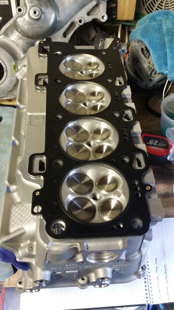
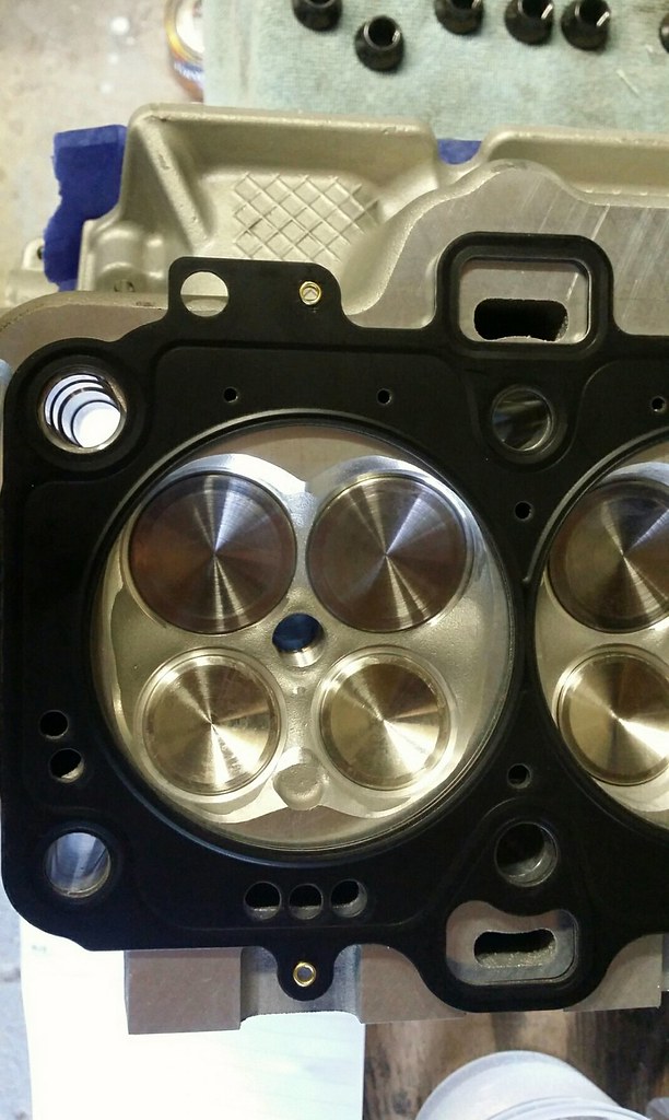
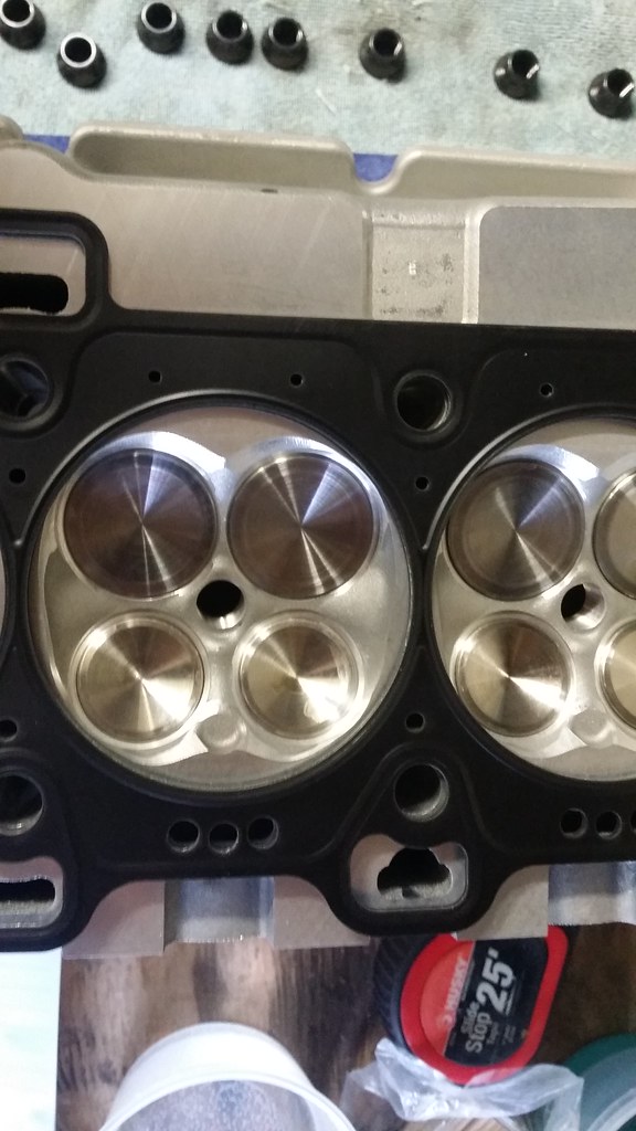
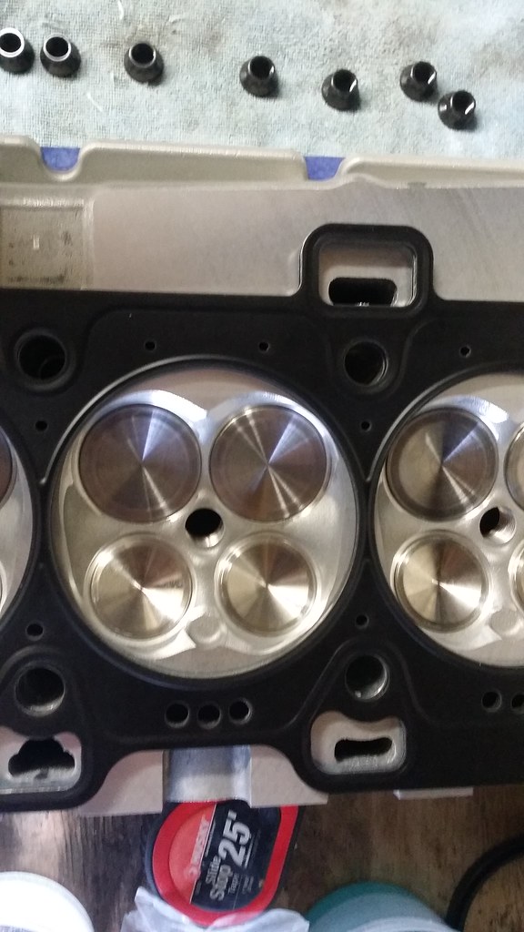
Back to the fun stuff. After I turned my attention away from math and back on putting parts on the car, I put all of the ARP studs back in. I went down to the bottom of the holes because if I turned them half a turn, they were wobbly as **** and it wasn't something I was confident in. Studs went back in the engine and out came the Cometic head gaskets for a 11-14 Mustang. After lining up the head gaskets on the heads, it looks like everything lined up and is all set. So in case anyone is wondering. 2015 heads fit on the 11-14 block and with 11-14 head gaskets without issues.
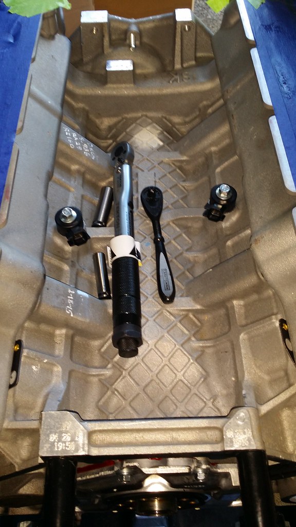
Head gaskets got put on the deck and then the heads got put onto the block followed by the ARP washers and ARP nuts. As per ARP instructions I used the ARP assembly lube and put some on the threads of the studs as well as the nuts. It may have been overkill but oh well. I asked around bout the torque procedure at Tim Eichhorn over at MPR Racing Engines told me what he uses for the ARP bolts.
Parts List
2015 Heads - FR3Z-6049-A
2015 Heads - FR3Z-6049-B
Cometic 94mm Bore MLS .040" Gasket Right - C5286-040
Cometic 94mm Bore LMS .040" Gasket Left - C5287-040
ARP Head Studs 11-12 Block - 256-4702
Torque Specs
Step 1 - Hand tight
Step 2 - 30lb-ft - I waited an hour before continuing on
Step 3 - 30lb-ft again
Step 4 - 50lb-ft
Step 5 - 70lb-ft
Step 6 - 90lb-ft
Step 7 - 110lb-ft
Step 8 - Wait an hour and 110lb-ft again
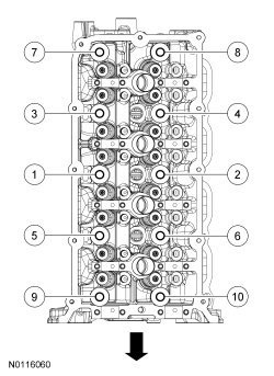
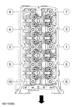
Follow the head stud torquing sequences below for each side
Right Hand
Left Hand
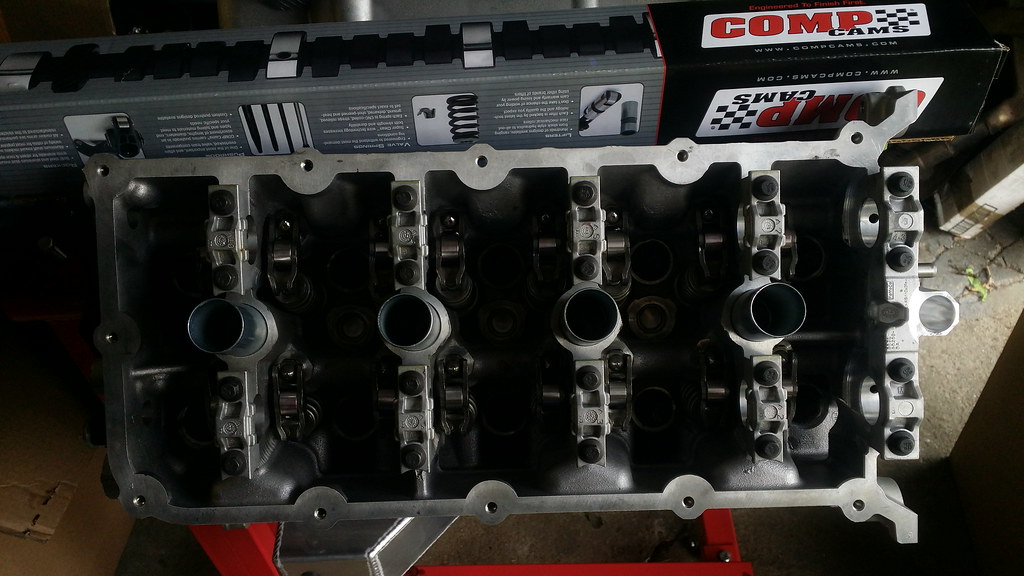
Here it is in all its glory with the heads on the block now.
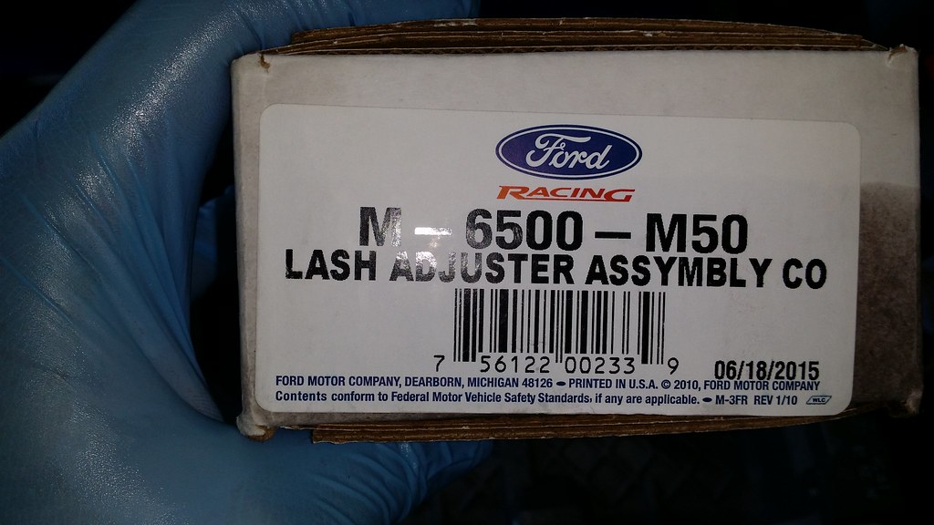
As I said eariler, the heads come bare without followers of lash adjuters. In pricing them out, I found it cheaper to go with the newly released FRPP kits rather than buy them separately. So I went ahead and grabbed the boxes for my parts pile.
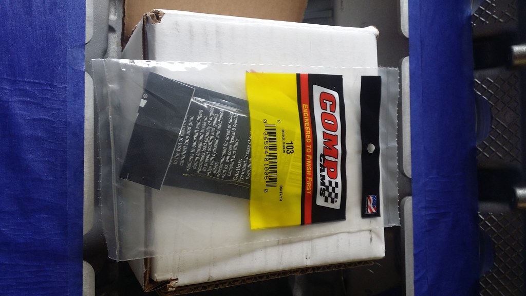
I started with the lash adjusters and put a very small amount of Comp assembly lube #103 on the lash adjuster and plopped them in their respective holes.
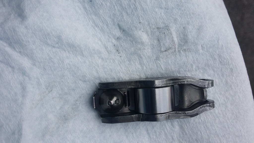
Next thing was to grab the followers and get those into place. They are pretty easy to install, just roll them on the lash adjusters until you hear them click. Before you put them on, always remember to clean your parts even if they are brand new. As you can see here, these are straight out of the box and they are dirty.
Very nice Sean. She's coming along very well.
Keep up the good work!
Thanks Tony! Wait until you see the ending though
Originally Posted by Jazzman442
Bring me back to the days of building race motors for fun.. Great write up one of the best I have ever seen.
Keep it up Subscribed!!
That's what I was hoping for. When I am all done with it I should be putting up a spreadsheet with part numbers and torque specs bolt sizes etc. to hopefully help people out in case they need to do something such as this.
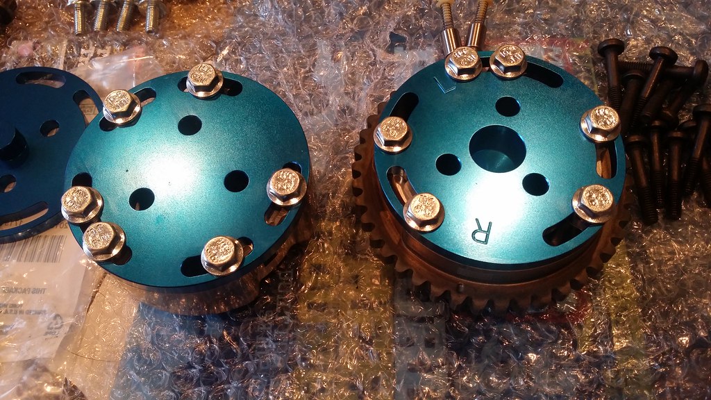
Now that I have the heads on and assembled I turned my attention towards the RGR lockouts. Now, I know there is a huge amount of what the hell are you doing when it comes to going with lockouts versus going with limiters but in talking with JPC, they didn't feel that I would be losing a lot of power with them and I could lock the cams in for higher RPM power on the race track. I have trusted them this far and I think performing as well as they do shows what they they know. Me being a complete noob at this, I have 120% faith in them on the decision. Plus they look pretty cool.
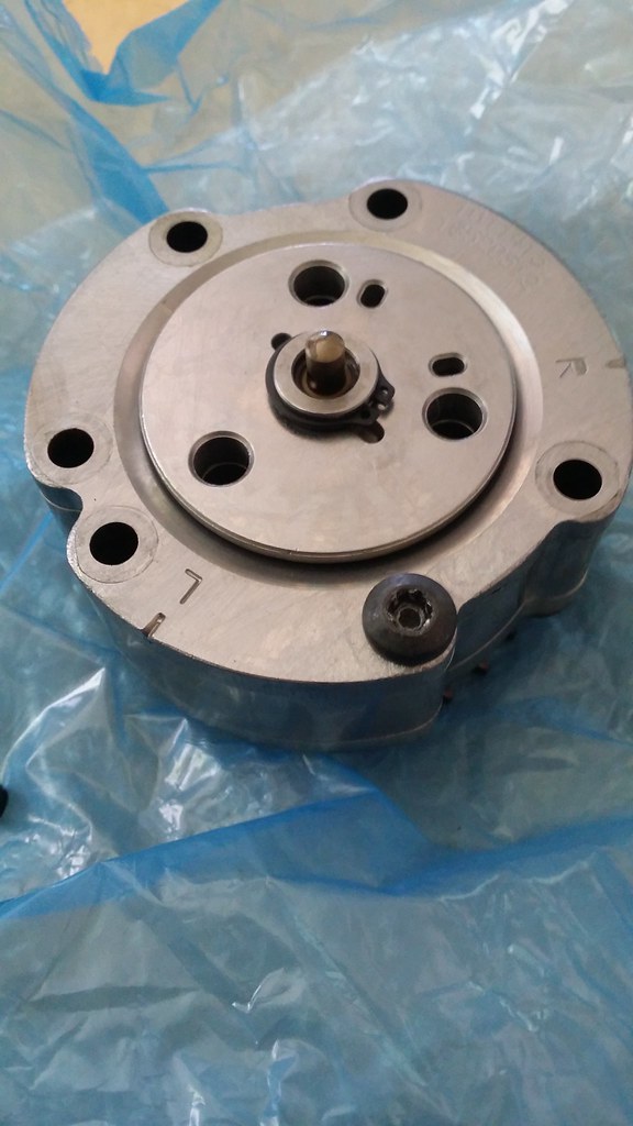
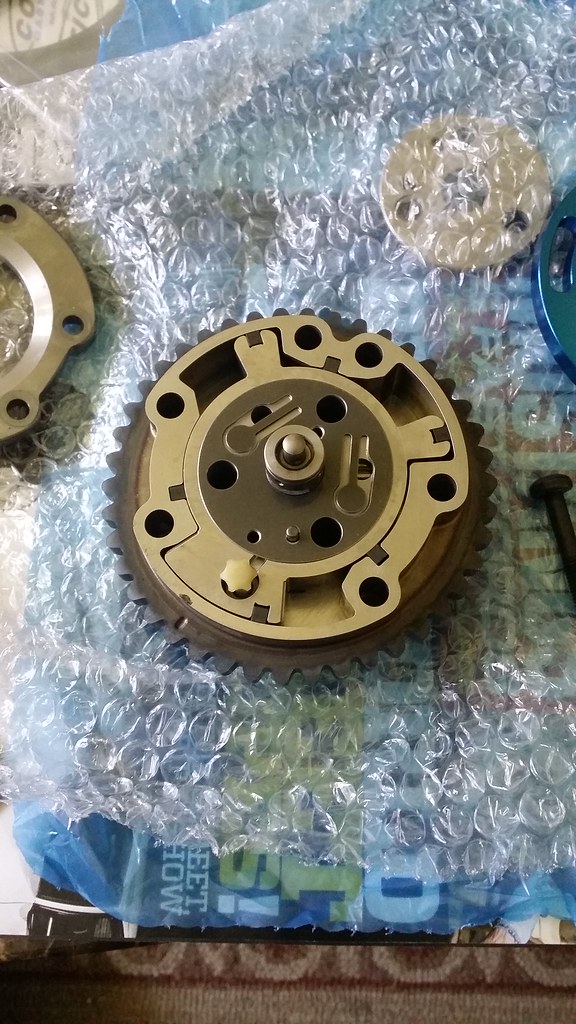
So, I grabbed the phasers out of the FRPP timing kit and went to work on them. First thing I did was mark my right & left timing marks with a magic marker. White out or scribing them probably would have been the easier and better thing to do but as long as you can mark them, that's all that matters. I found it easier to take the snap ring off first and then take the torx bolts off but don't take the last bolt out all of the way, only a couple of threads and then place it on a flat surface.
From there you can now take the last bolt off all of the way from the housing, and take off both plates.
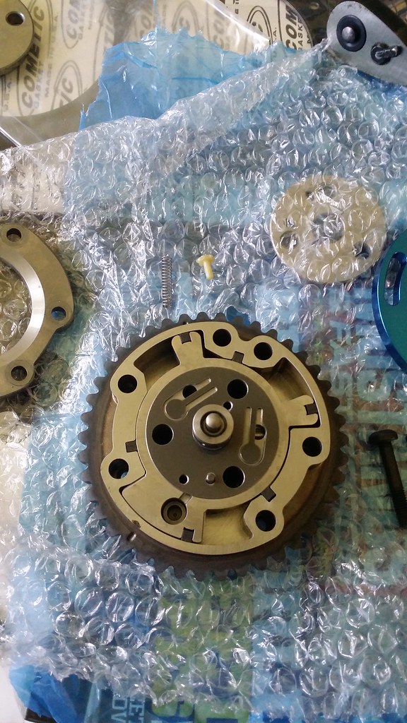
The next thing to do would be to remove the plastic piece along with the spring
From there you want to dispose of the "guts" of the phaser. You might want to grab a towel or a plastic bag and put it over the phaser and separate the bottom part with the middle section and let the internals come out.
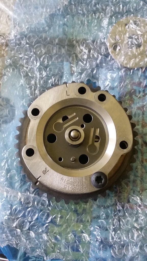
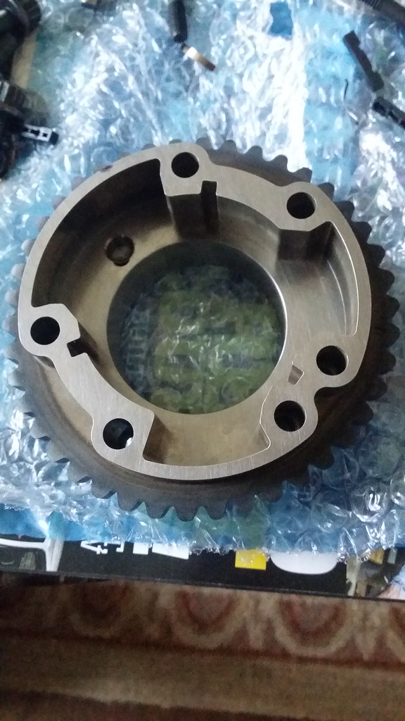
Now you can put the phasers on. For your exhaust phaser, you take the middle section and the bigger delete plate and put those together to make the exhaust phasers. For the intake phasers, you grab the back plate and the small delete plate and put those together.
From here, you can now begin to put the cams in.
Parts Used
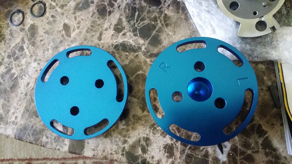
RGR Phaser delete plates
The next thing on the list was to put the cams in. First things first, make sure you have new cam filters and make sure that you have new cam bolts as these are TTY bolts and you might not realize that. Now that we have that out of the way, we can go ahead and start with our cams. Make sure that you have the orientation correct. The comp cams are labeled RI, RE, LI & LE right on the boxes so it is pretty easy to identify which is which.
I just want to take the time to say that I have heard a couple of times that the aftermarket cams are not gun barrel drilled like the factory or CJ cams are. It doea however appear that my cams are drilled out in the center which will reduce some rotational mass. I do wish that I weighed them compared to my stock Boss cams but I had chucked them long ago as they were all messed up and probably had bearing material in them.
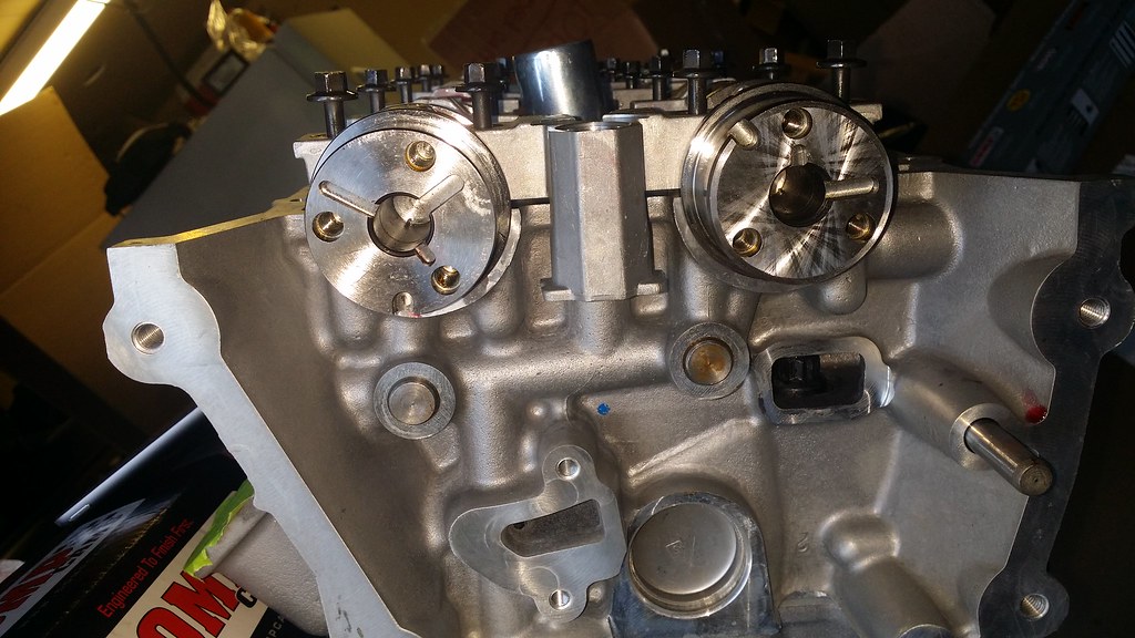
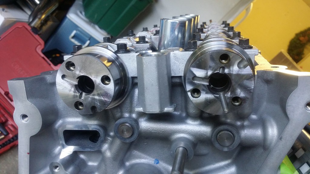
When you put the cams in you want to make sure that they are in the neutral position with the D hole in the following positions.
Left side
Right side
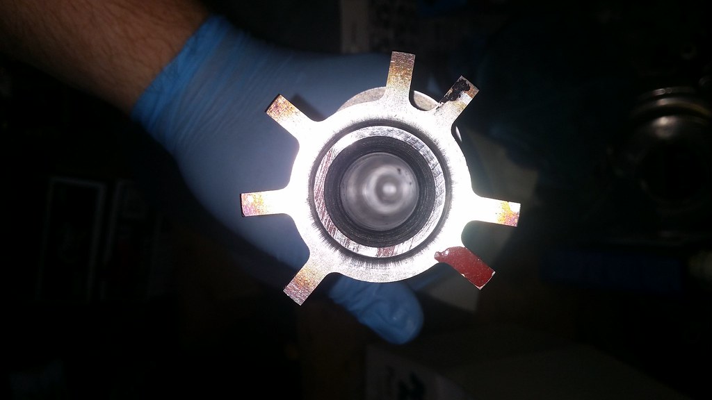
From there you can put the new cam filters in, but remember to clean out the bores of them so they are nice and clean. This is a picture before I cleaned them. As you can see it is slightly dirty haha.
Cam bolts get torqued down now once you have both cams in the heads. Don't forget to put the Comp Assembly lube on the cam journals and cam caps.
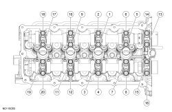
This is the torque sequence for both left and right heads.
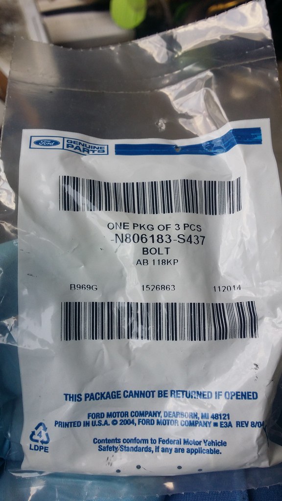
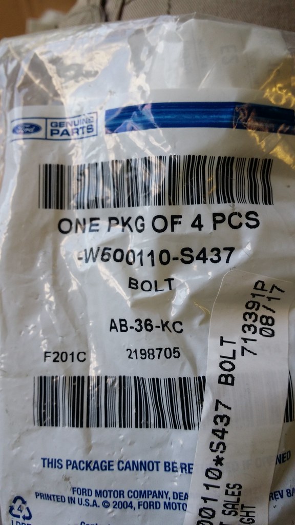
Cam Cap Bolts - N806183-S437 ( You need 40 of these)
Comp Cams Camshaft Assembly lube - 103
Torque Specs
Step 1 - 53lb-in
Step 2 - additional 45 degrees
Remember to follow the above sequence when torquing down your cam caps!!
This is where I ****ed up. I snapped 2 bolts because I was looking at the torque specs for the head bolts, not the cam cap bolts so make sure you follow the specs listed and don't do something stupid like I did. I bothered Eric over at JPC about it when I realized my mistake so thank you to him for tolerating my stupidity.
This is where I ****ed up. I snapped 2 bolts because I was looking at the torque specs for the head bolts, not the cam cap bolts so make sure you follow the specs listed and don't do something stupid like I did. I bothered Eric over at JPC about it when I realized my mistake so thank you to him for tolerating my stupidity.
Awesome build thread!
I made a similar mistake one time when bolting the pressure plate to the flywheel in the Corvair. I read the flywheel to crank spec and after snapping two PP bolts, figured out what I was doing wrong.
I made a similar mistake one time when bolting the pressure plate to the flywheel in the Corvair. I read the flywheel to crank spec and after snapping two PP bolts, figured out what I was doing wrong.
It is a terrible feeling when you do it too. On the second one it snapped inside of the cam cap thread and I **** near shot myself haha. Thankfully I was able to get it out though, but yeah no fun haha.
I wanted to go ahead and take a break from the top end and get the little things out of the way that the service manual says to do.
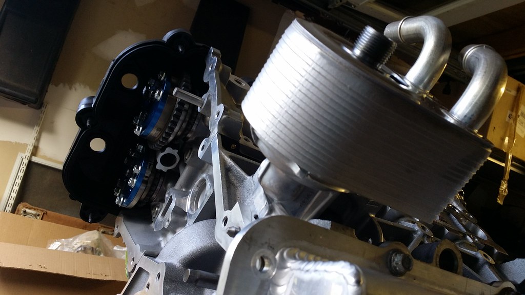
So, I went ahead and grabbed my coil covers and put those on to prevent any debris form falling into the heads as well as grabbing the oil filter adapter with new gasket already installed and the three bolts and torqued them down. I went ahead and grabbed my new Boss oil cooler out of the box and went ahead and installed that as well.
I will be keeping the factory Boss 302 oil cooler despite everyone saying that it is nothing but an oil heater. When Ford Racing and Cooltech LLC were doing testing on their kits they found that they were able to keep the oil cooler with a smaller oil cooler in series with the factory oil cooler rather than if you had went with a larger oil cooler by itself. Cooltech uses the Setrab 172 oil cooler while Ford Racing uses the Setrab 915 oil cooler. For the time being I am going to be running the factory oil cooler and once it warms up a bit I will decide on which oil cooler to use as well as try and box in the radiator and oil cooler for better cooling properties as the 2012 Boss's tend to run pretty hot on track.
Parts List
Oil Filter adapter bolt x2 - 10mm - W714974 (Sorry, I don't have the last digits on this one right now)
Oil Filter adapter bolt x1 - 10mm - W503306 (Sorry, I don't have the last digits on this one right now)
Ford Racing Boss 302 oil cooler - 14mm allen key - M-6642-MB
Torque Specs
Step 1 - 177lb-in
Step 2 - Additional 60 degree turn
Step 3 - Put oil cooler threaded fitting in and tighten to 43 lb-ft
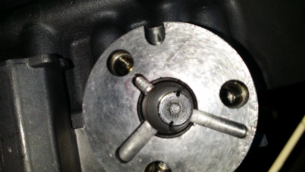
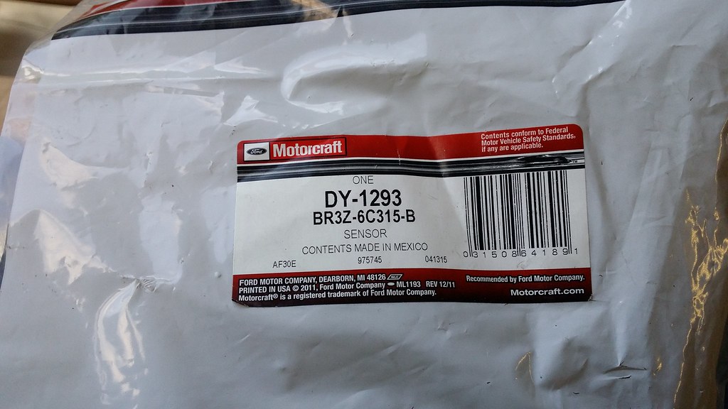
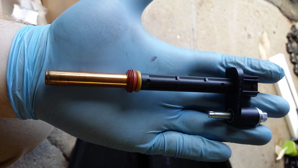
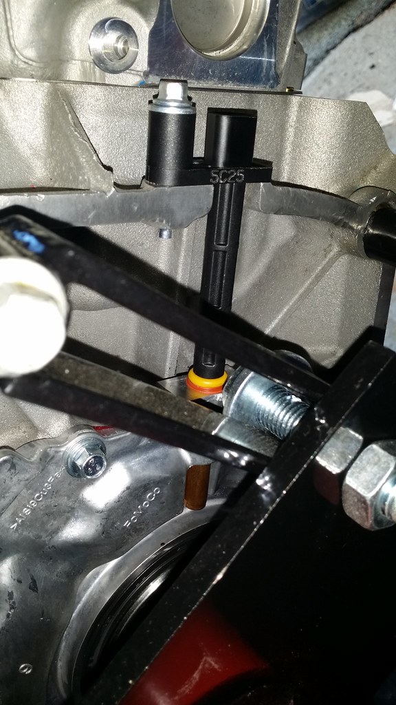
The next thing I did was grab the crankshaft position sensor and put that into place. This appears to be the revised one with the new O-ring installed that was addressed by the TSB 13-6-15.
NOTICE: The Crankshaft Position (CKP) sensor must be positioned into the fitting on the crankshaft rear seal retainer plate and be flush against the boss on the engine block before the bolt is installed. If the CKP (Crankshaft Position) sensor is installed incorrectly, the CKP (Crankshaft Position) sensor can be damaged.
Parts List
Crankshaft Position Sensor - 8mm - DY-1293 (Comes with a new bolt)
Torque Specs
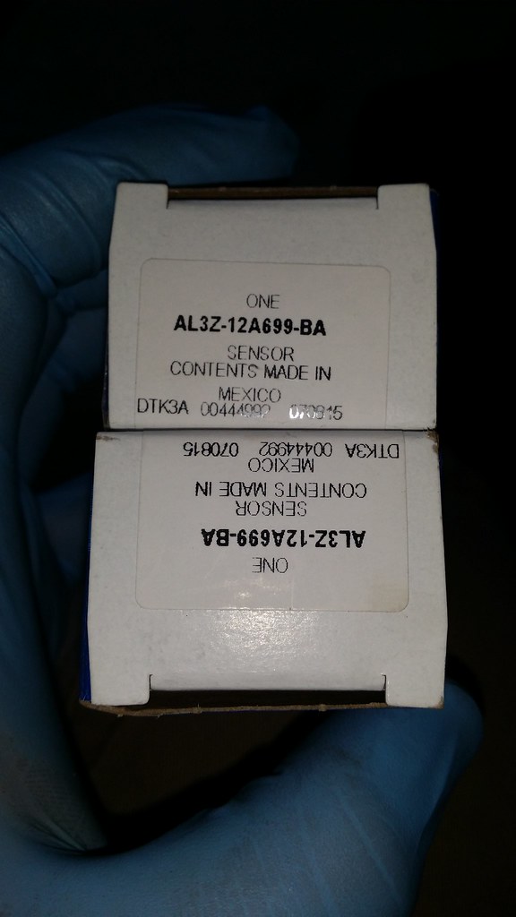
I went back to the top of the motor and grabbed the new knock sensors and went ahead and put those in as well. These point towards the rear of the engine.
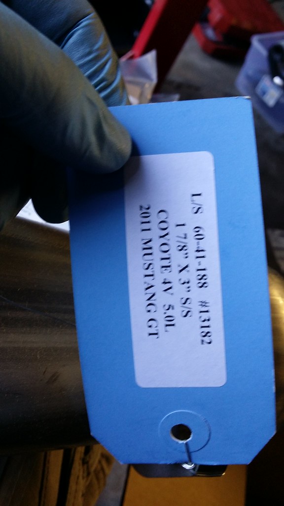
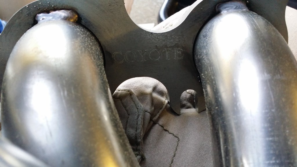
I worked my way down to the exhaust now as per the manual's instructions. So I went ahead and grabbed my long tubes out of the boxes.
First thing I did was grab the exhaust studs. Mind you, these are 2015 heads so I am not 100% certain if the studs are interchangable or if they have the same part number as the 11-14 heads.
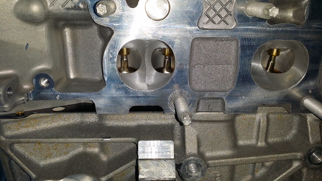
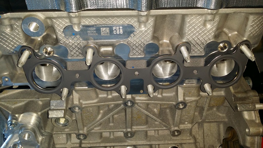
Then I went ahead and grabbed the gaskets for 2015 heads. Just a quick shot of the exhaust valves before I put them on. Very nice looking
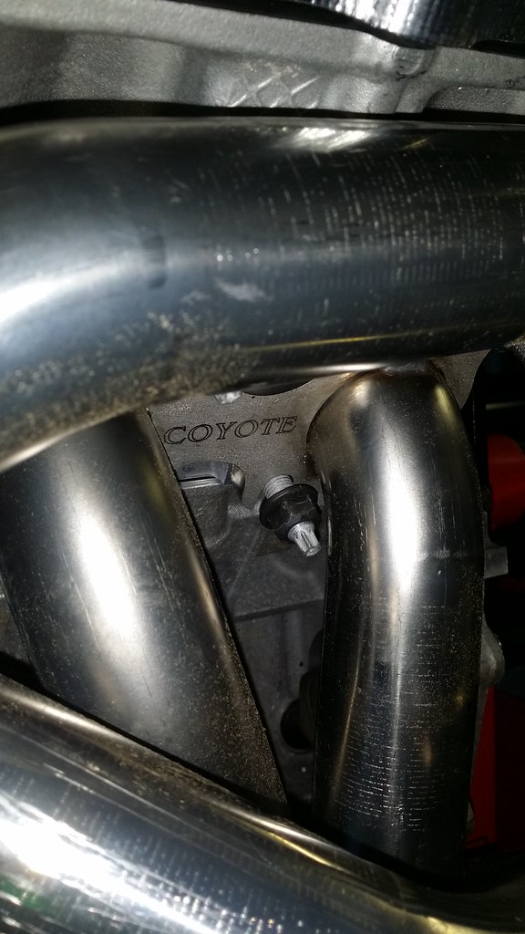
I put the long tubes on followed by the nuts for the studs.
Some of them like this one were pains in the behind I will admit.
Parts List
Kooks 1 7/8 x 3 - 11412400
Exhaust Manifold Studs 2015 - 6mm - W714869-S431
Exhaust Manifold Nuts - 15mm - W714870-S430
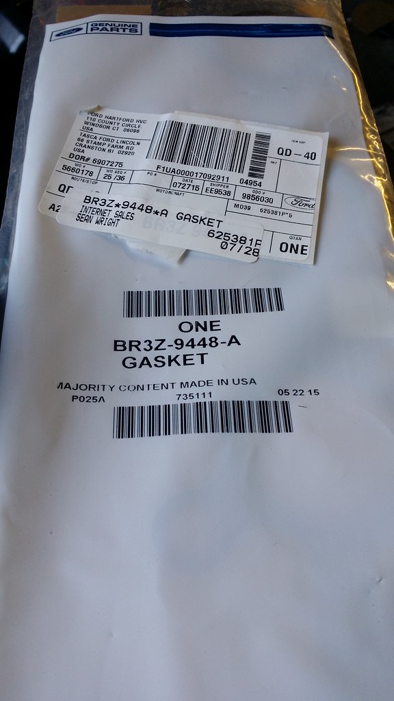
Exhaust Gaskets - BR3Z-9448-A
Torque Specs
Exhaust Studs - 18lb-ft
Exhaust Nuts - 2 Steps
Stage 1 - 18lb-ft
Stage 2 - 24lb-ft
****, I don't know what you guys are *****ing about. Installing headers is ****ing cake, bunch of pansy's .....
I don't see why you wouldn't be able to. I was able to bolt all of mine down and torque the bolts I could reach down to spec. The other ones I did with German torque specs and it seemed to work for me. When it comes to headers I am a big fan of all factory hardware and gaskets.
I just want to highlight the fact that I went ahead and purchased a set of MPR Heavy duty secondary timing chains. They feature larger pins that connect the chains so there is less chance of a pin snapping under high stress. If I am remembering correctly the heavy duty secondary chains also have a thicker inner and outer plates. With the added RPM's and Trick Flow Springs I felt it would be a nice addition to have on the motor to have a little bit of added security.
So basically what we are doing in this process is timing the motor. What I first did was grab my MPR Billet Crankshaft Sprocket and slide that onto my crankshaft.
Then, I grabbed the RGR lightweight phaser deletes along with the MPR Heavy Duty Secondary Timing Chains and I oriented the chains in the way they should be facing. For the LH phasers they should be oriented in this direction:
The timing mark on the intake VCT (Variable Camshaft Timing) assembly should align between the 2 consecutive colored links.
The timing mark on the exhaust VCT (Variable Camshaft Timing) assembly should align with the single colored link.
From there you put the phasers on the camshafts (intake phaser next to the intake ports and exhaust phaser next to the exhaust ports) making sure the timing mark on the exhaust phaser is in the 11 o clock position and go ahead and grab your primary timing chain. From there you can bolt up the phasers to the cams using the VCT bolts.
Once you have them bolted in you can put the primary chain on making sure that the colored links are in line with the timing marks on your exhaust phaser as well as the crank sprocket.
Note that this last picture is only a demonstartion of the color link being lined up with the mark on the crank sprocket. The primary chain for the LH side goes on the back of the sprocket and the RH side goes on the front of the sprocket.
Then you can put on the timing chain guide on the LH side. You might have to rotate the crankshaft a little bit in order to get enough slack to put it on then you can slide on the tensioner arm.
It took me a while to get the glue off from this sticker before I hit it with WD-40 and all the adhesive came right off. This is the timing chain guide BTW.
Since I bought the Ford Racing Camshaft Drive Kit I got brand new everything so I didn't have to depress the Boss tensioners back into position. In case you need to depress yours here is the proceedure:
NOTICE: Do not compress the ratchet assembly or damage to the tensioner will occur.
1. Compress the primary timing chain tensioner plunger, using an edge of a vise.
2. Using a small screwdriver or pick, push back and hold the ratchet mechanism, then push the ratchet arm back into the tensioner housing.
3. Install a suitable pin into the hole of the tensioner housing to hold the ratchet assembly and plunger in place during installation. Most people I know use a paperclip as a pin.
New Boss 302 Tensioner
Once you have the tensioner installed you can do the same thing to RH side of the engine as the procedure is the same except that the timing mark the exhaust phaser should be facing the 1 o clock position.
Keep in mind, this is not a step by step guide, but more so a general overview of the steps needed to time the engine. Once all the marks are set the engine is timed if you are not going to degree cams. If you are going to degree them, than you still have to actually degree the cams.
Parts Used
Ford Racing Coyote Camshaft Drive Kit - M-6004-A504
I ended up talking to Eric over at JPC before they left for the NMRA race at Bowling Green in the beginning of October about degreeing the exhaust cam. He ended up telling me the process to get them degreed and I got the exhaust cam all situated and degreed in after about 5 or 6 hours on Saturday the 3rd. On Sunday the 4th I came out side and started getting my baseline measurements. My neighbor came over and started asking me about the cams to see if I had it figured out since he helped me get the intake cam degreed. I guess I had thought I tightened everything down because I started turning the motor over but then after a while I realized that the cam had spun to the other side as the bolts on the phasers were now on the far right side of the phaser instead of the far left where I had set it. I stopped and put the cam back in the position as it was before and went to go get the measurement again but this time I was something like 12 degrees off of where it was before it spun. So I turned the motor over to make sure the timing marks all lined up and they all did, except for the left secondary chain so EVERYTHING had to come back off. I pulled everything off and retimed the motor and went to go degree my intake cam again. The motor then began to bind up but then it just stopped I turned it in the other direction and it began to bind up again and then it stopped.
In all honesty, I can't tell you the feeling of defeat I felt at that moment. I stopped what I was doing and put the bag back over the engine and walked inside. I just sat down and that was it. I was done for, lost all motivation for finishing my car for awhile. I spoke with JPC and they will finish the motor for me. I have to talk to them about bringing the entire car down and having them finish it all off for me. It would have been a cool feeling to have done it myself but I think I am over my head now. I hope I didn't bend a valve or crack a piston or something.
After owning the car for 2 years and 3 months a year and a 2 months, the car has been without an engine and 8 months prior to that it was barely driveable with CPS issues and VCT actuator issues and random misfires and phantom CEL's so I just want it done and over with to be honest. Thankfully I have the winter to get everything taken care of though.
 1/5/16, 02:44 PM