FACTORY HID ON AN 05 !!!GOT IT DONE!!!
 6/21/10, 06:32 PM
#1
Member
Thread Starter

Join Date: July 31, 2007
Posts: 31
Likes: 0
Received 0 Likes
on
0 Posts
FACTORY HID ON AN 05 !!!GOT IT DONE!!!
i JUST FINISH WITH THE CONVERTION OF THE OEM HID FOR MY 05 MUSTANG. i HAD TO REPLACE THE LIGHT HARNESS AND JUMP 2 WIRES WITH SOME DIODES. IT WORKS PERFECT LOW HIGH AND FLASH TO PASS. WHAT A GREAT MOD. I DO HAVE AN EXTRA SET OF GT500 LIGHTS AND THE HARNESS IF ANYONE WHANT TO DO IT. HERES A PIC.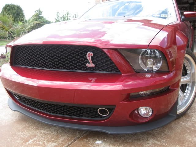

 6/21/10, 08:32 PM
#4
Team Mustang Source
Here's an overview of the wiring mods required if anyone's interested:
Here is the entire harness assembly as it comes from Ford (note the big light gray/dark gray box on one end, that's the connector that plugs into the bottom of the fusebox, and it's where the surgery takes place):

The lt gray cover unsnaps by releasing 4 very obvious locking tabs. The connectors slots inside are numbered 1-12 the long way and A-F across (i.e. 1A is in the lower left corner of the photo):

There are two rails of green plastic slats the double lock the harness contacts into the housing. These must be slid out:


Once that's done, you need to release the contact in slot 9A and move it to (currently empty) slot 8D (this provides power to the second relay in the HID harness) The contact can be released from the connector body by carefully releasing the plastic tab that holds it in with a small pick or jewelers screwdriver from the non-wire side:


Now, two rectifier diodes must be soldered in to bridge the connection at 2A to F7 and A6 to F6. In both cases, the band on the diode must face the connector in the "A" row. (The diodes act like one way valves for electricity, and keep the light arc powered when you switch to high beam mode). I don't prefer to solder near spring type connectors, as I've found the heat can damage the plating and change the tension properties, so I soldered the bridges between the existing wires and about 2" back from the connectors. Use a pair of needle nose pliers to prevent excessive heat soak from harming the diodes:


The second diode goes in place between the appropriate connectors much the same as the first. The connections should then be insulated to preclude any chance of shorting to other wires/connector pins. In my case I had some very tiny split loom on hand, so I used that, along with some liquid tape (a sort of brush-on rubbery insulator) to seal the ends:

That's basically it for the needed mods. reassemble the connector assembly and replace the lt gray cover. From here it's basically a swap and replace of the original harness from the fuse box to the lights.
DISCLAIMER: This is based on the instructions developed and published online by SilverHorse Racing. Like them, I'm posting this for informational purposes only, and am not responsible for any damage to anyone's car should they attempt to follow this and something goes wrong.
Here is the entire harness assembly as it comes from Ford (note the big light gray/dark gray box on one end, that's the connector that plugs into the bottom of the fusebox, and it's where the surgery takes place):
The lt gray cover unsnaps by releasing 4 very obvious locking tabs. The connectors slots inside are numbered 1-12 the long way and A-F across (i.e. 1A is in the lower left corner of the photo):
There are two rails of green plastic slats the double lock the harness contacts into the housing. These must be slid out:
Once that's done, you need to release the contact in slot 9A and move it to (currently empty) slot 8D (this provides power to the second relay in the HID harness) The contact can be released from the connector body by carefully releasing the plastic tab that holds it in with a small pick or jewelers screwdriver from the non-wire side:
Now, two rectifier diodes must be soldered in to bridge the connection at 2A to F7 and A6 to F6. In both cases, the band on the diode must face the connector in the "A" row. (The diodes act like one way valves for electricity, and keep the light arc powered when you switch to high beam mode). I don't prefer to solder near spring type connectors, as I've found the heat can damage the plating and change the tension properties, so I soldered the bridges between the existing wires and about 2" back from the connectors. Use a pair of needle nose pliers to prevent excessive heat soak from harming the diodes:
The second diode goes in place between the appropriate connectors much the same as the first. The connections should then be insulated to preclude any chance of shorting to other wires/connector pins. In my case I had some very tiny split loom on hand, so I used that, along with some liquid tape (a sort of brush-on rubbery insulator) to seal the ends:
That's basically it for the needed mods. reassemble the connector assembly and replace the lt gray cover. From here it's basically a swap and replace of the original harness from the fuse box to the lights.
DISCLAIMER: This is based on the instructions developed and published online by SilverHorse Racing. Like them, I'm posting this for informational purposes only, and am not responsible for any damage to anyone's car should they attempt to follow this and something goes wrong.
6/22/10, 01:50 PM
#6
Team Mustang Source

Still feeling sort of like hell physically, but I pushed through the pain to get it done. Totally worth the effort...
I want to acknowledge Pedro (Cubican) as a great pal and truly thank him for both the nudge to tackle this, and his assistance in getting me hooked up with the parts needed.
Last edited by Torch_Vert; 6/22/10 at 01:51 PM.
6/22/10, 05:35 PM
#8
Team Mustang Source
Nah, no real problems. Once the wiring mods were done, changing the harness out was pretty direct swap and replace. Having to pull the bumper off is obviously the biggest part of the work. If I was feeling better it would have been a snap, but as it was, it was semi-challenging.


Thread
Thread Starter
Forum
Replies
Last Post
Fred_Garvin
2010-2014 Mustang
4
9/17/15 04:10 PM