When you click on links to various merchants on this site and make a purchase, this can result in this site earning a commission. Affiliate programs and affiliations include, but are not limited to, the eBay Partner Network.
*SOLVED*
Passenger window stopped working, checked the plug to the motor and getting power. I got a new motor, it didn't work. I returned and got a new one in case this one was defective and motor still wont work. I was able to track down a wiring diagram and this I get from the 8 pin plug going to the motor. Could the Auto Up/down be the culprit? Driver's side is completely fine.
Tan w/lt blue - 12v when down button
White w/yellow - 12v when up button
Red/lt blue - constant 12v
Violet w/Blue nothing (auto)
Brown w/lt blue - constant 8 volts
Gray w/Red - constant 12v
Yellow w/Green - constant 12v.
hmmmm . . . . maybe it needs to be programmed somehow? maybe the reset procedure, which involves running the window all the way up and down and holding the button or something like that . . . but if the window won't respond at all then obviously you cannot do that . . . . I dunno?
From your post:
Correct: Tan w/lt blue - 12v when down button Correct: White w/yellow - 12v when up button Correct: Red/lt blue - constant 12v, delay accessory (the 10 minute thing unless doors are opened after switch is off) Correct: Violet w/Blue nothing (auto) INCORRECT: Brown w/lt blue - constant 8 volts, This is the motor power itself. This should be 12V, it's coming from the BEC directly and is a 30 amp fuse. Correct: Gray w/Red - constant 12v, but I don't know what GOC is, but being it's lower power amp circuit, I'm going with memory for the up/down locations? Correct: Yellow w/Green - constant 12v, Door's open, lights are on, drop is on. Close the door, this goes off, the drop goes back up, if applicable.
I suspect your incoming motor power is compromised and you need to investigate that. And I'd suggest you go investigate the other door's motor's wiring and compare, perhaps that'll shed some light. But excepting that one, it sounds like all is otherwise in order power/signal wise...
Perhaps the regulator is binding? Just a thought...
Brown w/lt blue was actually like 8.5v.. I rechecked it, it's steady at 9.1v., very odd. .I rechecked the fuse, it's good. Even swapped it out with the driver's side. I checked the voltage at the fuse terminals, both sides at 12.2. I never installed the new motor, just plugged it in to verify if it was working. . i was thinking maybe the signal from the driver's side was stuck closed so I unplugged the driver's switch to check it that way. Still investigating. I will have to take apart the driver's side and see whats on that side.
Yes, pin # 8 is ground. My test results were using the ground from the plug. Before i take the Drivers door apart. I'm going to try putting 12 volts to the motor itself. Who knows, maybe they gave me the same motor back.
Update.
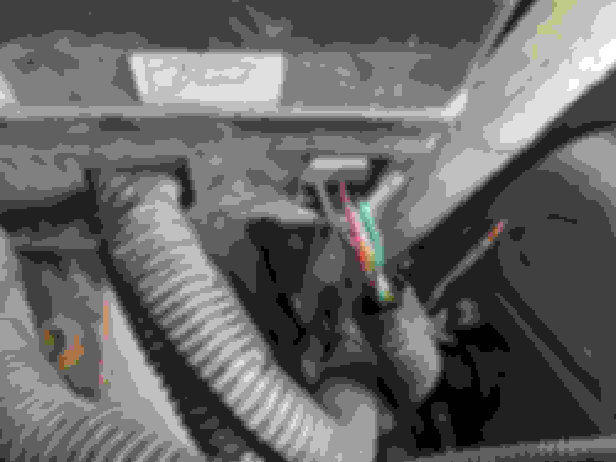
Finally got around to putting power to the motor. You cannot just put 12v to the Up/Down pins. It appears there is a relay inside the motor housing. You have to put 12v to the Brown w/Lt blue pin on the motor side. Then you can put 12v to the Up/Down pin. The 9V on the Brown w/lt blue from the plug was of course the issue. I got lucky and found the faulty wire. At the fuse box, there is a bundle of wires coming out. It was right at the exit point. I re-spliced it and all is working again. You can see the green oxidation around the exit point. For some reason this bundle was not wrapped all the way up like the others. Perhaps vibrations from the wire against the box cut into it.. Thanks for your help.
does anyone have a 8 pin diagram of the 8 pin wiring plug showing where number 1 is and the rest of the numbers as i am trying to find out why a new motor on the passenger side rear quarter window still does not work on my 05 mustang thanks in advance
does anyone have a 8 pin diagram of the 8 pin wiring plug showing where number 1 is and the rest of the numbers as i am trying to find out why a new motor on the passenger side rear quarter window still does not work on my 05 mustang thanks in advance
Check out the repair and service help sub forum section... You can submit questions and locate threads which are directly related to service and other related repair/technical issues...
Thread link is also provided below as well.
I have a 2005 mustang convertible and just replaced the power top motor but am not getting any power to the motor from the top switch even with new relays so is the switch bad or something else
If You Dig into the Pdf's in Here It gives Some Diag on the Whole Convertible top Integration With The Window Motors. A Reader Which Can Pull Body Codes Would Be Helpful!
I Would Venture To Say if The Window Motor Worked Before Power Top Motor Install Then Something Was Torn Loose in The System During The Process. Could Have Been a Limiting Switch or a Wire Broken Etc.
I Added More Info To The Last Post For Your Issues as it Ties into The Top as A Whole For Future Information Seekers!
Rereading Your Posts It Appears You Have a Quarter Window Motor Issue and Then a Top Motor Issue. Unclear Is It One or the Other or Both???? Anyhoo Hopefully This Thread Has Enough Info To Give You Some Idea of How the System ties Together.
I have both problems as when we first got the car the windows all worked but the top did not as the original owners disconnected the side shocks from the frame and made it a manual top so I tested the top motor behind the rear seat and it was bad so I replaced the motor and now when you put 12 volts to it the motor works but I am not getting any power to it from the switch so I replaced the switch and still no power and after testing there is no power coming to the switch yet all the fuses are good plus the relays are good so I don�t know what else to do except try to put another switch in the wire going to the motor and mount the switch up front next to the driver but don�t know if that will work without relays in the system. The other problem was the right rear power window motor stopped working so I replaced it and still not working so after some testing it appears that it lost constant power to the brown wire so I used a jumper wire to another brown wire with a blue stripe that is only hot with the key on and connected it to the brown wire and when I hit the button on the driver door to test the motor the window went down only than all the rest of the windows were dead and would not work plus the stereo went dead. Why the stereo was connected to the same circuit as the windows is confusing as I thought it should be on a separate circuit so I ran a new power wire from the battery to both brown wires on that same right rear motor and now everything works except now the radio is always on so I am really confused as what to do so PLEASE HELP ME
Have You Looked At The Wiring Diagrams I Supplied in The Last Post of The Link Above? Also Now in This Post, Actually The Whole Thread is a Good Education on How The Whole System Works. As Suggested You Should Get a Scanner To Check For Body Codes Which May Point You in the Right Direction. Many Parts Houses Will Scan Your Car For Free Just Make Sure They Can Pull Not Just DTC Codes Buy Body Codes. I Would Not Be Surprised if You Had Water Intrusion into SJB Causing Issues as it is Tied into System. If So A Cleaning of The Pins May Do The Trick.
May Want To Go Through and Print Out Some of The Relevant Items Especially The Wiring Diagrams.
It's a Lot of Information So Take Your Time, Relax and Think it Through Before Diving in at Random! Have Your Doc's at The Ready. I Really Think if You Can Get Some Codes it Will Really Help. May or May Not get Any But Worth a Shot! It's a Complex System Where Everything Has to Be Working Correctly or The Whole Shebang Goes Fubar. One Little Wire or Connection or Hidden Trigger Switch can Also Be at Play!
As Far As The Radio You Did Not Say if It Was a Factory Radio With Factory Wiring or Has it Been Replaced and Possibly Wired Incorrectly?
It’s a aftermarket radio that was just fine until this happened so it’s not the radio or the wiring plus where is the link for the wiring diagram as I would like to see them thanks
It�s a aftermarket radio that was just fine until this happened so it�s not the radio or the wiring plus where is the link for the wiring diagram as I would like to see them thanks
on another issue does anyone have a diagram showing the convertible top side hydraulic shocks showing where on the frame it connects as I got the bolts to reattach them but all the way extended they are not long enough to reach the frame so is there a part missing that I need
Update.
Finally got around to putting power to the motor. You cannot just put 12v to the Up/Down pins. It appears there is a relay inside the motor housing. You have to put 12v to the Brown w/Lt blue pin on the motor side. Then you can put 12v to the Up/Down pin. The 9V on the Brown w/lt blue from the plug was of course the issue. I got lucky and found the faulty wire. At the fuse box, there is a bundle of wires coming out. It was right at the exit point. I re-spliced it and all is working again. You can see the green oxidation around the exit point. For some reason this bundle was not wrapped all the way up like the others. Perhaps vibrations from the wire against the box cut into it.. Thanks for your help.
Might pay to address the rust forming on / around the bolt??

 7/1/20, 02:02 AM