
Shaftmasters 3.5" Driveshaft Install (w/pics)

Thread Starter
Legacy TMS Member
Joined: May 24, 2006
Posts: 7,409
Likes: 0
From: San Diego
Shaftmasters 3.5" Driveshaft Install (w/pics)
This 'How-To' will cover the installation of the 3.5" Shaftmasters 1-piece aluminum driveshaft with adapter plate.
For those with the replacement pinion flange kit, see step 10 for further instructions.
Tools required
Various metric sockets (10, 12 (12 point), 13, 18mm)
12mm (12 point) ratcheting box end wrench (optional)
12mm (12 point) crows foot extension
8mm Hex-bit socket
Universal joint socket
Socket extensions (various lengths)
Blue Loctite
Torque wrench (up to 76 lb-ft)
Long flat blade screwdriver (or equiv. pry tool)
Rubber mallet (optional)
Brake cleaner (or equiv.)
Straight edge razor blade
Masking tape
Permanent Marker
Estimated install time: 2 hours
Installation
1. Jack the vehicle up as high and safe as possible. Always use jack stands!
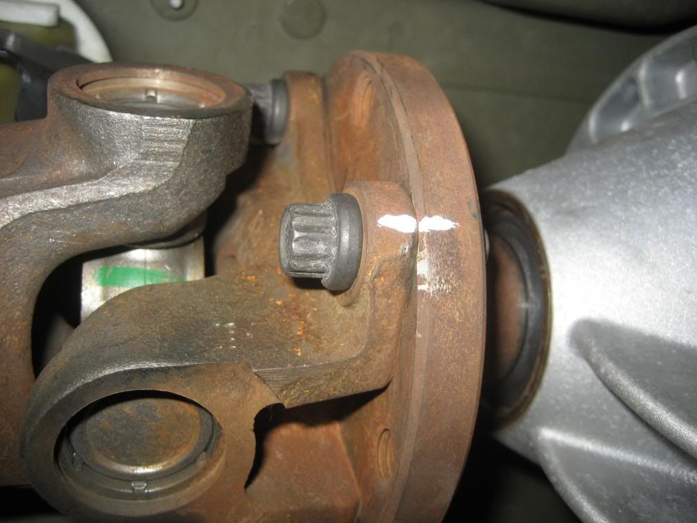
2. Using a permanent marker (I used paper 'white-out'), index mark the forward transmission output flange and the rear pinion flange (2 reasons, note the clocking of these 2 marks so the new aluminum driveshaft will be indexed as the OEM shaft, and incase you ever have to re-install the OEM shaft).
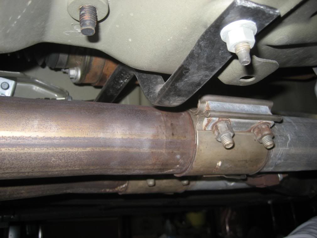
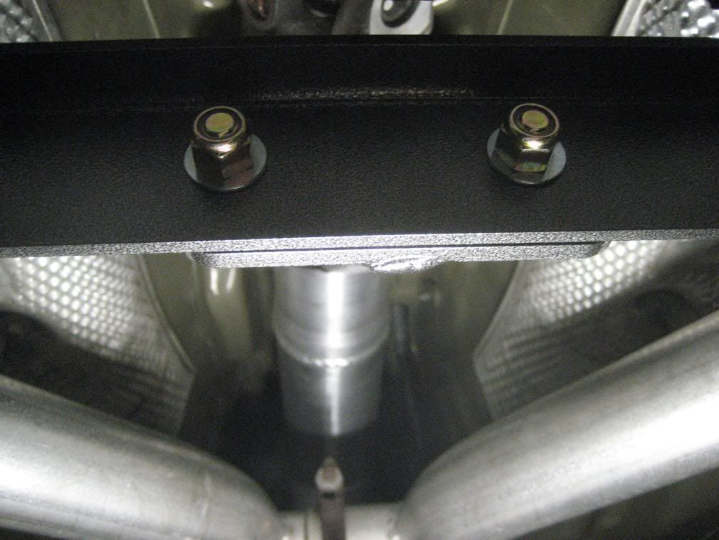
2A. If equipped, remove the driveshaft brace directly below the center carrier. It can be removed with the exhaust in place. This brace will not be used with the Shaftmaster.
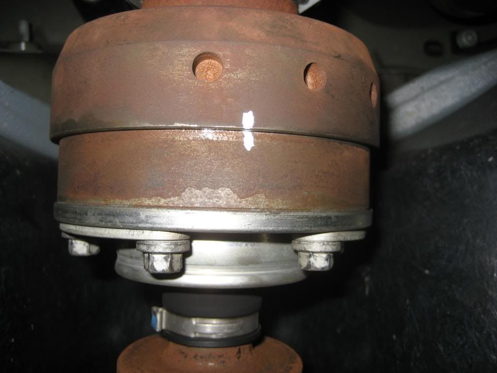
3. With the transmission in neutral, e-brake off, rotate the driveshaft (or have a helper turn the rear tire) for best access to the rear CV bolts. Set e-brake (so the bolts can be removed).
4. Using a 10mm socket, remove the (6) CV joint bolts.
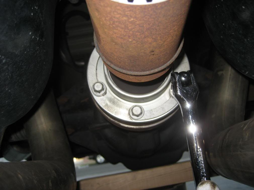
5. Using a 12mm (12 point) socket (or ratcheting wrench), remove the 4 driveshaft flange bolts from the transmission output flange.
Note: Release the e-brake and put in Neutral to rotate the driveshaft as necessary to gain access to the bolts. Do not forget to set the e-brake (may need to engage in Park for Auto tranmissions).
Note: Save these 4 bolts, they will be re-used.
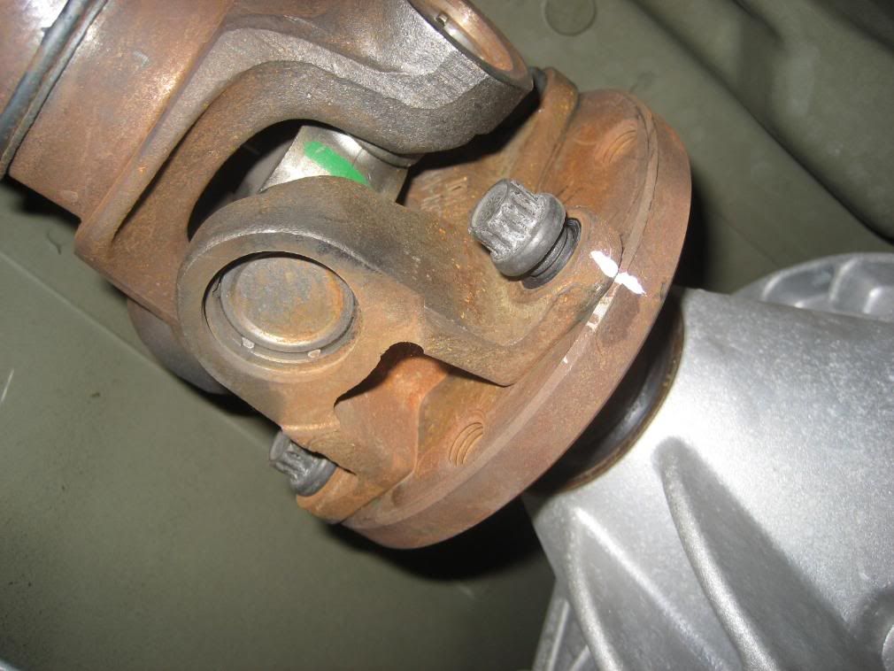
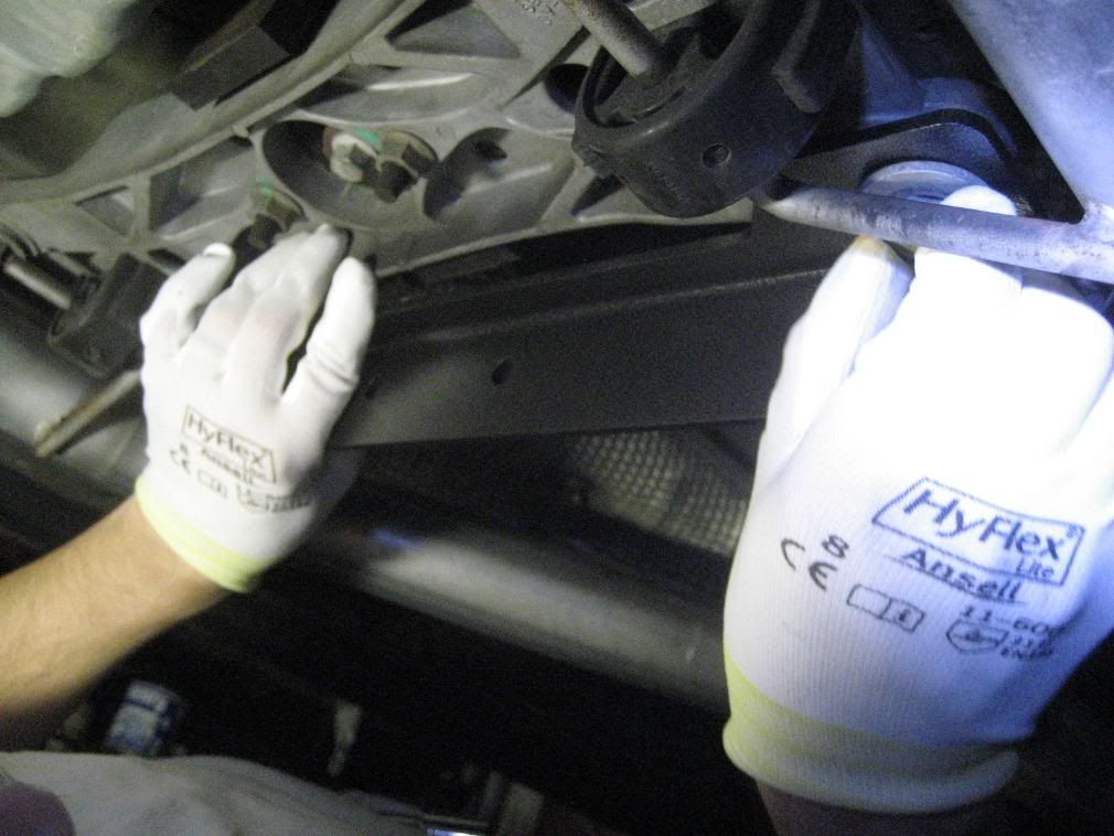
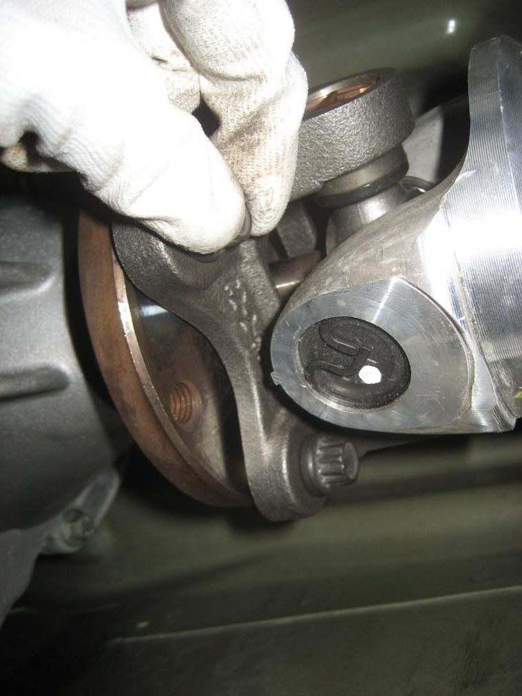
6. Using a suitable pry tool (a flat blade screwdriver worked fine for me), insert it into the U-joint at the position shown. The driveshaft will compress slightly to allow the driveshaft flange to disconnect from the transmission flange.
Use care not to damage or mar the transmission flange.
If unable to wedge anything in, use a rubber mallet to break the contact between the U-Joint and flange (PB Blaster (or equiv.) may be necessary to loosen up any rust keeping it from separating).
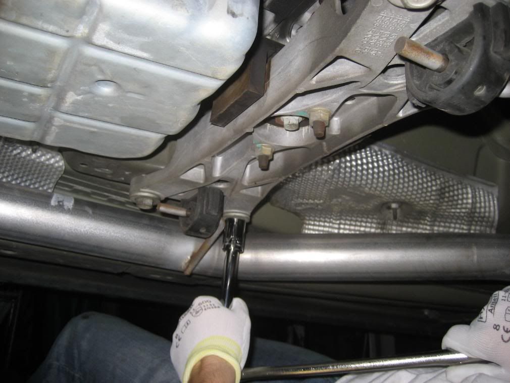
7. Place a couple pieces a 2x4's on top of the mid-pipes to keep the driveshaft from falling onto the pipes once the center bearing bracket is loosened.
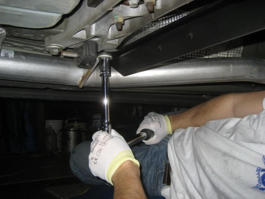
8. Using a 13mm socket (and universal joint adapter if required), remove the 2 bolts from the center bearing bracket (located about mid-way on the driveshaft).
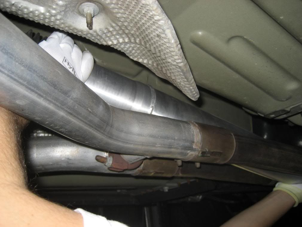
9. Driveshaft is now completely unbolted from the vehicle and now can be positioned to be removed through the rear in-between the mid-pipes.
10. Preparation for new driveshaft installation
Note: If you have the replacement pinion flange kit, see Driveshaft Pinion Flange Install (w/pics) for installation instructions.
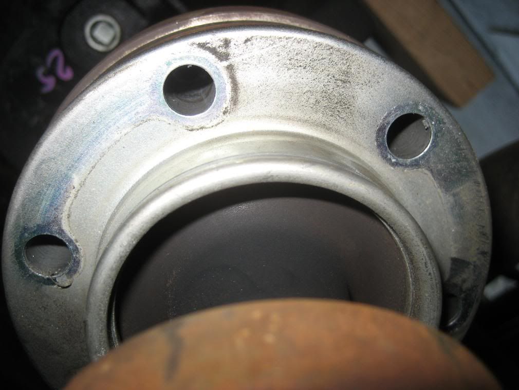
A thorough cleaning must be done on the rear pinion flange prior to the installation of the adapter plate. The adapter is machined to an interference fit, so to have it mate against the pinion flange without any debris (Loctite, grease, etc.) in-between is critical!
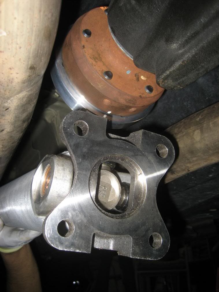
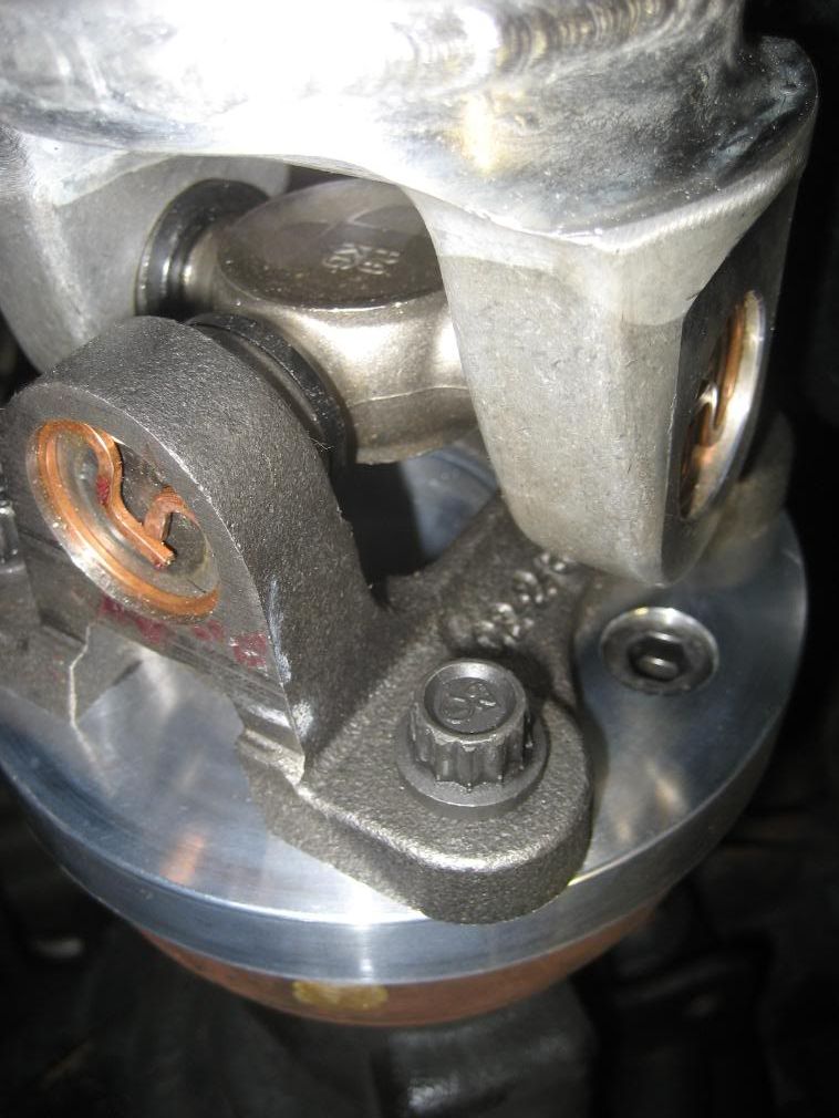
Using a plastic scraper and/or single edge razor, carefully scrape off any dried thread locker off from the pinion flange.
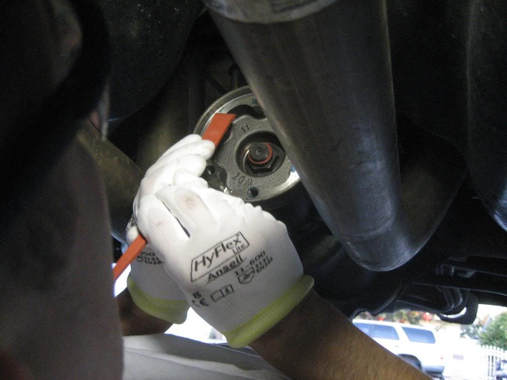
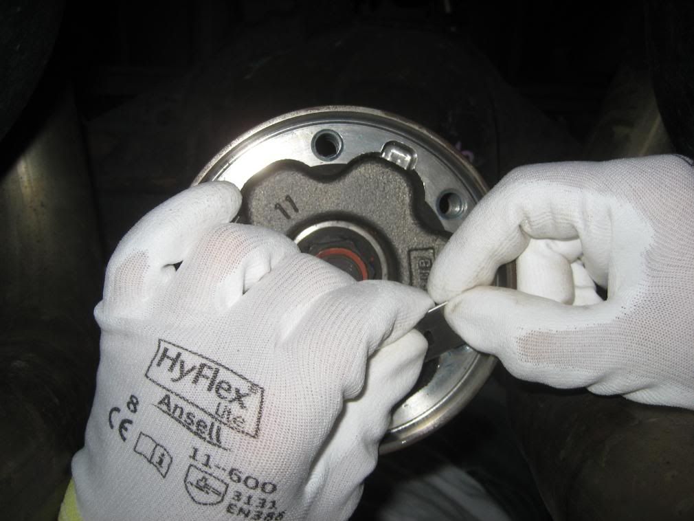
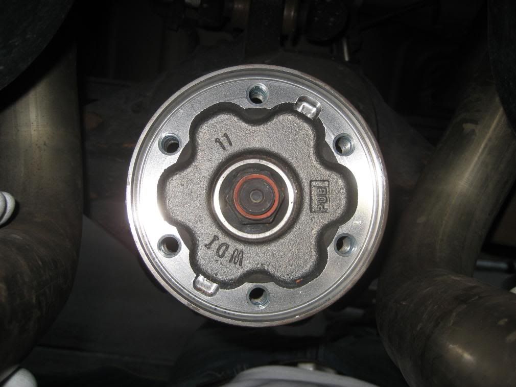
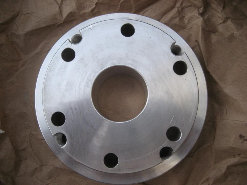
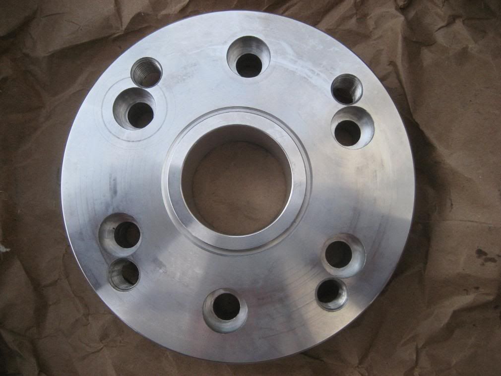
Pinion flange should look as clean as this.
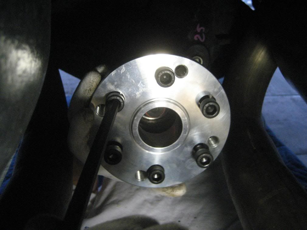
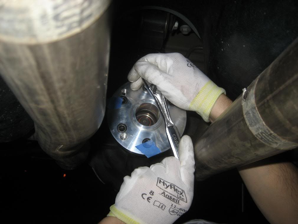
10A. Position the adapter plate into the pinion flange and using the 6 provided hex head bolts, evenly draw the adapter into the flange using a standard 'star' torque pattern until all 6 bolts are tight (but, not torqued).
Note: Do not put any Loctite on these bolts yet, must be installed dry at this time to avoid any Loctite from dripping in-between the adapter and pinion flange (Yes, it's that critical!).
Note: To ensure the adapter is fully and evenly seated onto the pinion flange, rig up a magnetic dial indicator (or hold stationary anything non-metallic) and have a helper turn the tires to check for flatness/trueness on the face of the adapter.
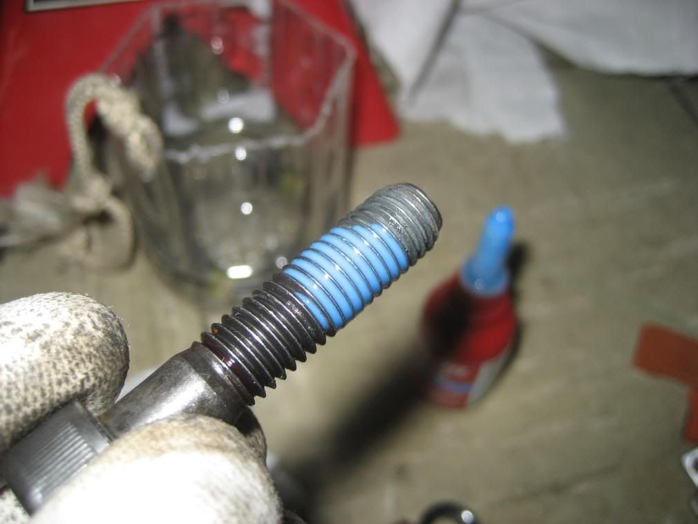
10B. Once the adapter plate is fully seated, remove one bolt at a time and apply Loctite on the threads, re-install, and torque to 41 lb-ft.
Note: I used a piece of masking tape to mark each bolt that I Locktited and torqued to avoid any confusion.
BMR front safety loop
Whether you need a safety loop is all up to you.
Here's NHRA's take on it..
A driveshaft loop will be required on all cars running 13.99 or quicker and utilizing slicks, except vehicles equipped with street tires running 11.49 or slower.
For those installing a BMR front safety loop, see the installation steps below.
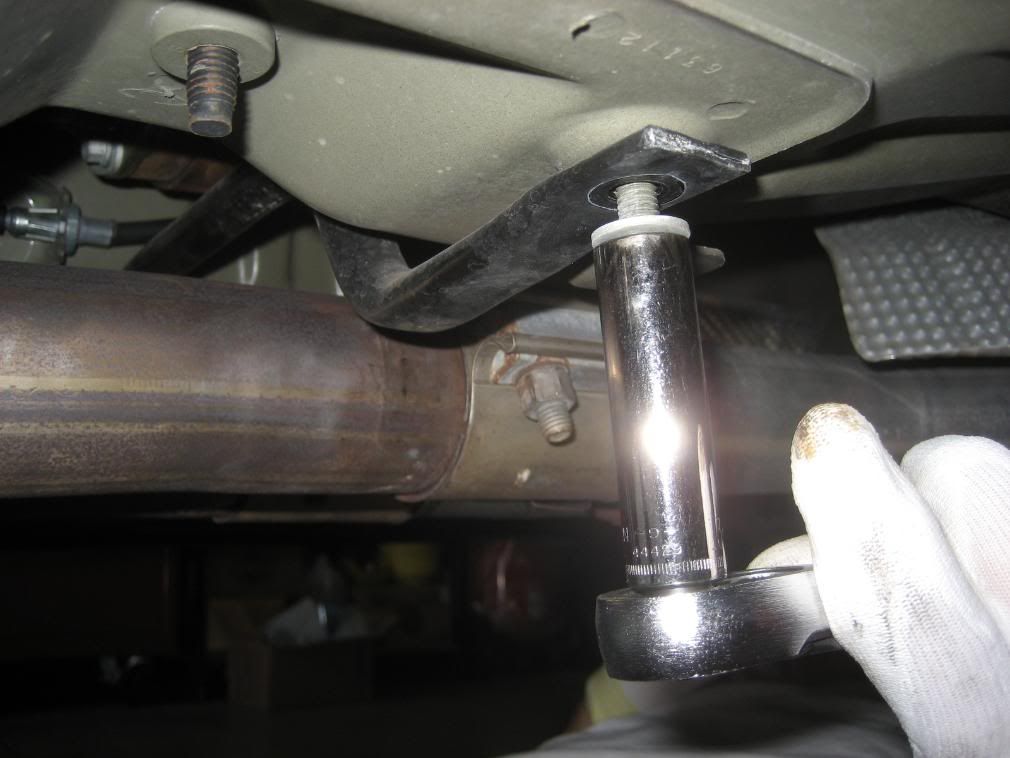
BMR1. Remove the 2 rear transmission crossmember bolts using an 18mm socket.
BMR2. Mount the BMR driveshaft loop mounting angle bracket to the transmission crossmember, re-install the factory bolts and torque to 55 lb-ft.
BMR3. Insert the new drive shaft though the BMR loop and let it hang until the 4 bolts on the driveshaft flange to the transmission output flange are installed and torqued complete.
(no picture)
BMR4. See after step 11.
11. New driveshaft installation
With the e-brake off, clock/index the white-out marks you made on the pinion flange and transmission output flange.
Position the new driveshaft up from the rear in-between the mid-pipes and carefully route up to the front (and through the BMR front loop, if applicable).
Place rags over any sharp objects to avoid scratching the new aluminum driveshaft.
Mate up both ends of the driveshaft's U-joints against the rear pinion adapter plate and the forward transmission output flange.
Rotate the driveshaft if necessary to pick up the previously used 4 bolt holes in the transmission output flange, and make sure the 6 o'clock markings didn't move while rotating the driveshaft.
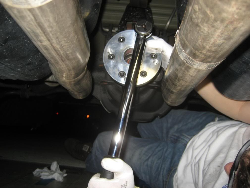
Once everything is in position, Loctite each bolt and snug down tight. Using a 'X' pattern, torque the bolts to the following;
Driveshaft to transmission output flange: 76 lb-ft
Driveshaft to pinion adapter plate: 41 lb-ft
Note: A standard socket / universal joint adapter / ratchet combo will not fit squarely on the U-joint bolts. Correctly torquing these bolts will be difficult without a 12 point Crow's Foot or short socket-U-joint combo (Snap-On has them).
If you choose to use a Crow Foot extension, use the following formula to set your correct torque value.
(T x L) / (L + E) = Adjusted torque value (what you set on your torque wrench)
T= target torque value
L= length of torque wrench in inches (end of handle to center of socket)
E= length of extension in inches (center of socket to center of bolt)
If using a 1" Crow's Foot extension on the front U-joint bolts, here's the way the formula works out.
(76 x 12" torque wrench) / (12" torque wrench + 1" extension) = 70.15 lb-in torque.
BMR4. Mount the loop portion to the crossmember angle using the supplied bolts and nuts. (no picture)
BMR5. Position the loop so it's even on both sides of the driveshaft (can use you fingers to check for even gap).
(no picture)
BMR6. Tighten the 2 bolts and ensure the even gap is maintained.
INSTALLATION COMPLETE!
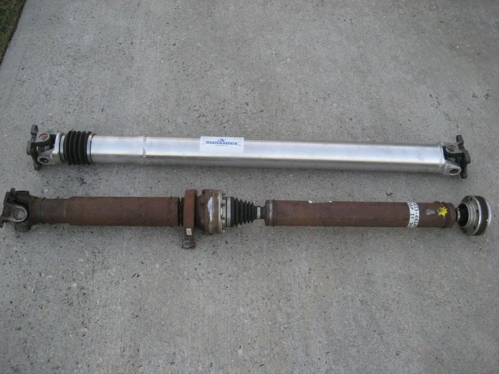
Baseline/comparison photos
For those with the replacement pinion flange kit, see step 10 for further instructions.
Tools required
Various metric sockets (10, 12 (12 point), 13, 18mm)
12mm (12 point) ratcheting box end wrench (optional)
12mm (12 point) crows foot extension
8mm Hex-bit socket
Universal joint socket
Socket extensions (various lengths)
Blue Loctite
Torque wrench (up to 76 lb-ft)
Long flat blade screwdriver (or equiv. pry tool)
Rubber mallet (optional)
Brake cleaner (or equiv.)
Straight edge razor blade
Masking tape
Permanent Marker
Estimated install time: 2 hours
Installation
1. Jack the vehicle up as high and safe as possible. Always use jack stands!
2. Using a permanent marker (I used paper 'white-out'), index mark the forward transmission output flange and the rear pinion flange (2 reasons, note the clocking of these 2 marks so the new aluminum driveshaft will be indexed as the OEM shaft, and incase you ever have to re-install the OEM shaft).
2A. If equipped, remove the driveshaft brace directly below the center carrier. It can be removed with the exhaust in place. This brace will not be used with the Shaftmaster.
3. With the transmission in neutral, e-brake off, rotate the driveshaft (or have a helper turn the rear tire) for best access to the rear CV bolts. Set e-brake (so the bolts can be removed).
4. Using a 10mm socket, remove the (6) CV joint bolts.
5. Using a 12mm (12 point) socket (or ratcheting wrench), remove the 4 driveshaft flange bolts from the transmission output flange.
Note: Release the e-brake and put in Neutral to rotate the driveshaft as necessary to gain access to the bolts. Do not forget to set the e-brake (may need to engage in Park for Auto tranmissions).
Note: Save these 4 bolts, they will be re-used.
6. Using a suitable pry tool (a flat blade screwdriver worked fine for me), insert it into the U-joint at the position shown. The driveshaft will compress slightly to allow the driveshaft flange to disconnect from the transmission flange.
Use care not to damage or mar the transmission flange.
If unable to wedge anything in, use a rubber mallet to break the contact between the U-Joint and flange (PB Blaster (or equiv.) may be necessary to loosen up any rust keeping it from separating).
7. Place a couple pieces a 2x4's on top of the mid-pipes to keep the driveshaft from falling onto the pipes once the center bearing bracket is loosened.
8. Using a 13mm socket (and universal joint adapter if required), remove the 2 bolts from the center bearing bracket (located about mid-way on the driveshaft).
9. Driveshaft is now completely unbolted from the vehicle and now can be positioned to be removed through the rear in-between the mid-pipes.
10. Preparation for new driveshaft installation
Note: If you have the replacement pinion flange kit, see Driveshaft Pinion Flange Install (w/pics) for installation instructions.
A thorough cleaning must be done on the rear pinion flange prior to the installation of the adapter plate. The adapter is machined to an interference fit, so to have it mate against the pinion flange without any debris (Loctite, grease, etc.) in-between is critical!
Using a plastic scraper and/or single edge razor, carefully scrape off any dried thread locker off from the pinion flange.
Pinion flange should look as clean as this.
10A. Position the adapter plate into the pinion flange and using the 6 provided hex head bolts, evenly draw the adapter into the flange using a standard 'star' torque pattern until all 6 bolts are tight (but, not torqued).
Note: Do not put any Loctite on these bolts yet, must be installed dry at this time to avoid any Loctite from dripping in-between the adapter and pinion flange (Yes, it's that critical!).
Note: To ensure the adapter is fully and evenly seated onto the pinion flange, rig up a magnetic dial indicator (or hold stationary anything non-metallic) and have a helper turn the tires to check for flatness/trueness on the face of the adapter.
10B. Once the adapter plate is fully seated, remove one bolt at a time and apply Loctite on the threads, re-install, and torque to 41 lb-ft.
Note: I used a piece of masking tape to mark each bolt that I Locktited and torqued to avoid any confusion.
BMR front safety loop
Whether you need a safety loop is all up to you.
Here's NHRA's take on it..
A driveshaft loop will be required on all cars running 13.99 or quicker and utilizing slicks, except vehicles equipped with street tires running 11.49 or slower.
For those installing a BMR front safety loop, see the installation steps below.
BMR1. Remove the 2 rear transmission crossmember bolts using an 18mm socket.
BMR2. Mount the BMR driveshaft loop mounting angle bracket to the transmission crossmember, re-install the factory bolts and torque to 55 lb-ft.
BMR3. Insert the new drive shaft though the BMR loop and let it hang until the 4 bolts on the driveshaft flange to the transmission output flange are installed and torqued complete.
(no picture)
BMR4. See after step 11.
11. New driveshaft installation
With the e-brake off, clock/index the white-out marks you made on the pinion flange and transmission output flange.
Position the new driveshaft up from the rear in-between the mid-pipes and carefully route up to the front (and through the BMR front loop, if applicable).
Place rags over any sharp objects to avoid scratching the new aluminum driveshaft.
Mate up both ends of the driveshaft's U-joints against the rear pinion adapter plate and the forward transmission output flange.
Rotate the driveshaft if necessary to pick up the previously used 4 bolt holes in the transmission output flange, and make sure the 6 o'clock markings didn't move while rotating the driveshaft.
Once everything is in position, Loctite each bolt and snug down tight. Using a 'X' pattern, torque the bolts to the following;
Driveshaft to transmission output flange: 76 lb-ft
Driveshaft to pinion adapter plate: 41 lb-ft
Note: A standard socket / universal joint adapter / ratchet combo will not fit squarely on the U-joint bolts. Correctly torquing these bolts will be difficult without a 12 point Crow's Foot or short socket-U-joint combo (Snap-On has them).
If you choose to use a Crow Foot extension, use the following formula to set your correct torque value.
(T x L) / (L + E) = Adjusted torque value (what you set on your torque wrench)
T= target torque value
L= length of torque wrench in inches (end of handle to center of socket)
E= length of extension in inches (center of socket to center of bolt)
If using a 1" Crow's Foot extension on the front U-joint bolts, here's the way the formula works out.
(76 x 12" torque wrench) / (12" torque wrench + 1" extension) = 70.15 lb-in torque.
BMR4. Mount the loop portion to the crossmember angle using the supplied bolts and nuts. (no picture)
BMR5. Position the loop so it's even on both sides of the driveshaft (can use you fingers to check for even gap).
(no picture)
BMR6. Tighten the 2 bolts and ensure the even gap is maintained.
INSTALLATION COMPLETE!
Baseline/comparison photos


Banned
Joined: November 30, 2007
Posts: 218
Likes: 0
Shaftmasters installation
David and I would like to thank Leo and Taco Bill for the how-to pictorial and excellant review of our product. We hope that this ends some of the myths circulating around the Mustang community relating to aftermarket aluminum driveshafts.
Myth #1. Aluminum shafts utilizing the adapter plate for GT's with automatic transmissions will vibrate or have NVH. FALSE!
Myth # 2.Spyderman is the only one who can build a decent aluminum driveshaft for the Mustang GT. FALSE! Although we have no doubt that the Spydershaft is a good product they are not the only ones who have the knowledge and experience to do so.
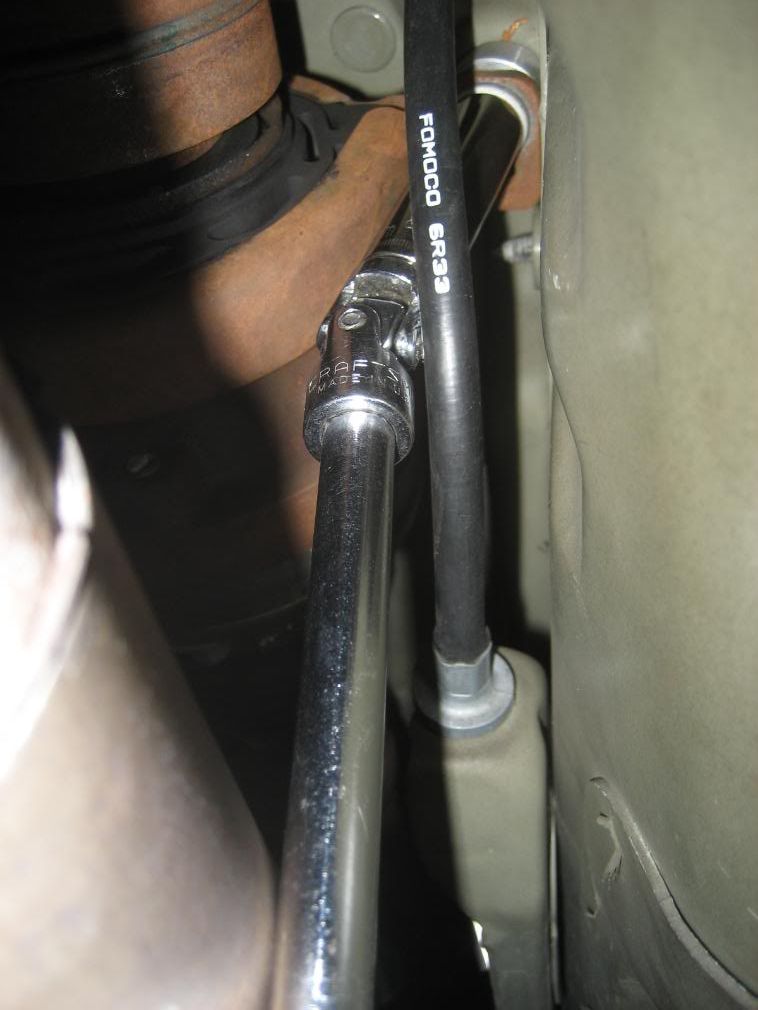
Myth # 3. The 1/4 inch of extra clearance that the 3.5 inch diameter shaft provides over the 4.0 inch diameter shaft makes little or no difference. False! We had a customer PM us this morning saying that on his 4.0 aluminum driveshaft he is experiencing the emergency brake cable rubbing on his driveshaft when he has passengers in the back seat .
An extra 1/4 inch of clearance would more than likely solve this problem. We don't want to be critical of the competition, we just want you to be open minded and give our product consideration.
Thanks for listening,
Robert and David
Myth #1. Aluminum shafts utilizing the adapter plate for GT's with automatic transmissions will vibrate or have NVH. FALSE!
Myth # 2.Spyderman is the only one who can build a decent aluminum driveshaft for the Mustang GT. FALSE! Although we have no doubt that the Spydershaft is a good product they are not the only ones who have the knowledge and experience to do so.
Myth # 3. The 1/4 inch of extra clearance that the 3.5 inch diameter shaft provides over the 4.0 inch diameter shaft makes little or no difference. False! We had a customer PM us this morning saying that on his 4.0 aluminum driveshaft he is experiencing the emergency brake cable rubbing on his driveshaft when he has passengers in the back seat .
An extra 1/4 inch of clearance would more than likely solve this problem. We don't want to be critical of the competition, we just want you to be open minded and give our product consideration.
Thanks for listening,
Robert and David
Legacy TMS Member
Joined: November 13, 2005
Posts: 2,193
Likes: 46
Leo:
Great write up! Definitely on my list for a future mod.
How about some feedback on your opinions re:
1) Any improvement over stock as far as NVH? (clunks, clanks, etc)
2) Any improvement in performance (via the Butt-O-Meter?)
Thanks!
Great write up! Definitely on my list for a future mod.
How about some feedback on your opinions re:
1) Any improvement over stock as far as NVH? (clunks, clanks, etc)
2) Any improvement in performance (via the Butt-O-Meter?)
Thanks!
legacy Tms Member
Joined: February 24, 2007
Posts: 490
Likes: 17
I'm sure that Leo will check in on his experience, but I have the 4" Shaftmasters on my car. Definite improvement over stock - I had a vibration before that is completely gone now, no sounds from the shaft and smooth driving. My car felt quicker as soon as I took it out, and when I went to the track I found that it was accelerating quicker - just with a change in the shaft I set a new personal best that weekend.
Thread Starter
Legacy TMS Member
Joined: May 24, 2006
Posts: 7,409
Likes: 0
From: San Diego
As far as performance goes the difference is amazing. The rpms's pick up so much faster. Accelration feels faster and smoother. I'm more than satisfied with all aspects of the DS and the level of customer service I recieved from Shaftmasters.
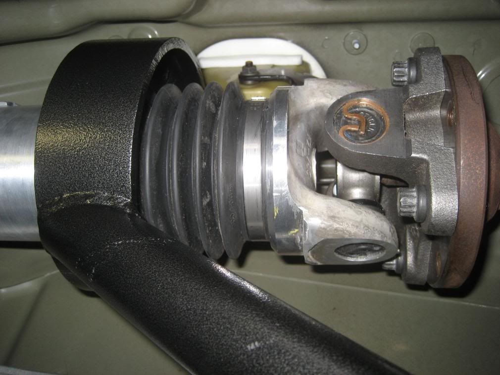
DS clearance- No clearance problems to report. More than inch clearance even next to the infamous "ebrake bracket". FYI- I have Steeda ultralite springs, auto tranny.
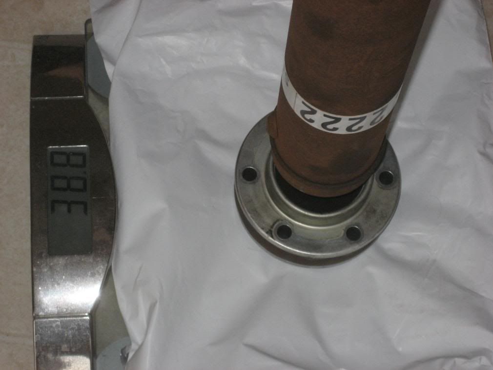
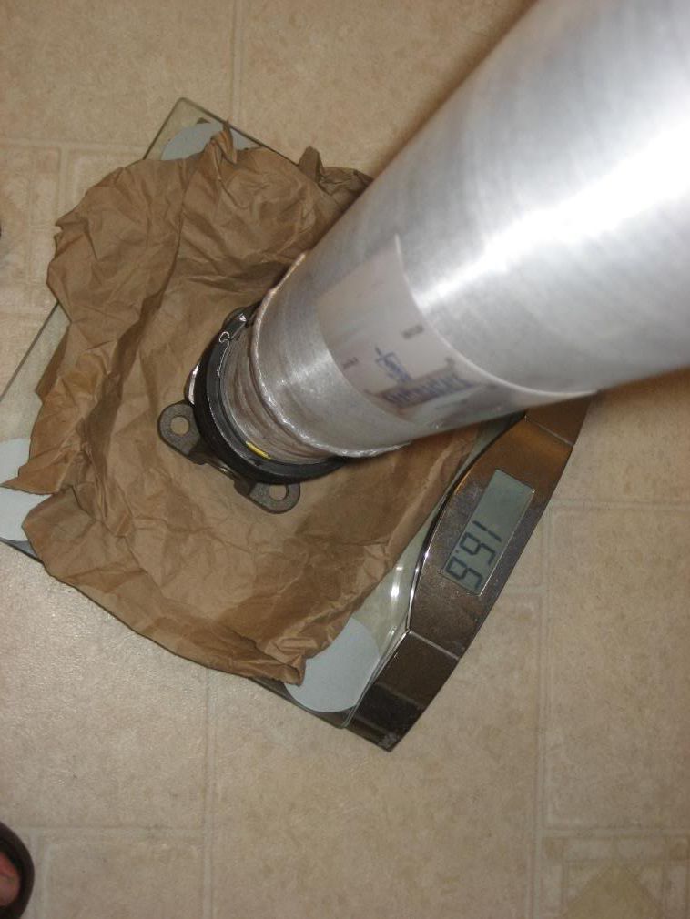
Weight difference-
After removing returning home today I weighed the stock DS and it came in at 38.8lbs while the Shaftmaster 3.5" aluminum shaft weighed in at 16.6lbs. That's a 22lb weight difference.
Track times-
Went to the track Friday night. Problem I ran into is that because of my 4.10 gears and the cold weather I wasn't able to get any traction. All my runs started with fishtailing which required me to left off the gas in order to avoid the wall. So because of that all my times were between 10-13 secs. FYI-It's a 1/8 mile track.
 So because of this I will not be able to provide an accurate difference before and after the ds install. What I can say though is that the DS definiatly registers in the butt-o-meter.
Thread Starter
Legacy TMS Member
Joined: May 24, 2006
Posts: 7,409
Likes: 0
From: San Diego
To tell you the truth I didn't measure it. Mainly because Tacobill has the drop kit as me and when he did his ds install his pa measured in at -2. So I figured I'd be fine.
Team Mustang Source
Joined: October 14, 2004
Posts: 738
Likes: 1
From: Dayton, OH
I have the same springs that you do and I don't want to order the UCA if I don't have too. I might just wait to order the UCA until I know for sure if I need it. Also, doesn't the pinion angle change as you are driving due to bumps and such? I would think that this would cause a issue with a 1 piece shaft.
Pinion angle is a reference measurement when the vehicle is in its static state on level gound.
Former Vendor
Joined: January 11, 2007
Posts: 2,594
Likes: 0
From: Aston, PA
David and I would like to thank Leo and Taco Bill for the how-to pictorial and excellant review of our product. We hope that this ends some of the myths circulating around the Mustang community relating to aftermarket aluminum driveshafts.
Myth #1. Aluminum shafts utilizing the adapter plate for GT's with automatic transmissions will vibrate or have NVH. FALSE!
Myth #1. Aluminum shafts utilizing the adapter plate for GT's with automatic transmissions will vibrate or have NVH. FALSE!
Myth # 3. The 1/4 inch of extra clearance that the 3.5 inch diameter shaft provides over the 4.0 inch diameter shaft makes little or no difference. False! We had a customer PM us this morning saying that on his 4.0 aluminum driveshaft he is experiencing the emergency brake cable rubbing on his driveshaft when he has passengers in the back seat .
An extra 1/4 inch of clearance would more than likely solve this problem.
An extra 1/4 inch of clearance would more than likely solve this problem.

CR
Tillman Speed, Inc.
610-497-5776

Thread
Thread Starter
Forum
Replies
Last Post
tj@steeda
2015 - 2023 MUSTANG
0
Sep 10, 2015 12:44 PM