When you click on links to various merchants on this site and make a purchase, this can result in this site earning a commission. Affiliate programs and affiliations include, but are not limited to, the eBay Partner Network.
Sorry no updates. haven't been able to play around with the switches. I do have the values from the 14 steering wheel switches for the left side. I have to fix or figure out why my front speakers aren't working and also my backup camera all of a sudden.
13-14 left side switch values:
On/off - is grounded = .5 ohms or less
Cancel/resume = 620-622 ohms
set - = 155 ohm
Set + = 353 ohms
5 way button:
Ok = 1350 ohms / 2.10 kohms
up = 366 ohms
Down = 890 ohms
Back = grounded 0/.5 ohms
Forward = 633 ohms
Forgive my ignorance here but wouldn't you be able to repin the connector on the steering wheel side to get it to match up to where they were originally going? And then add the resistor to that, if needed?
Forgive my ignorance here but wouldn't you be able to repin the connector on the steering wheel side to get it to match up to where they were originally going? And then add the resistor to that, if needed?
I have already done that from the start. top buttons left and right are fine as they have two wires each. the right side was the easiest to do while the top left not so easy. the bottom two are also a bit harder as each button has its own separate wires. all the s550 buttons are reading no where close to that of the s197 besides the top right. I'm not an electrical geniuses so I'm stuck right now till I have enough time to do more.
If you can tell me what resistors I would need that would help but I think I'm the only one that's swapped or trying to make the controls work. Ill post up what the S550 switches are reading later on today or tomorrow.
Yeah, thats what my friend was telling me, everything goes through the controller first and it translates it to the car, he said it would be very tough to get the cruise to work. That is my mine concern is the cruise.
Check out the thread in this section about adding the LED cluster. We had to modify the switches to get cruise to work by changing the resistors. Might help.
It has been about a month since the last check-in...any updates or changes?
Sorry nothing new to add. Been busy with work and getting everything ready for the new baby to arrive. Im hopeing I get to play around with it next month since I'll be taking at least a week off but then again it all depends on the kids lol.
Sorry everyone its not the update you were waiting for but this is gonna be on hold for awhile. Unfortunately my cars clutch, hopefully just the throw out bearing since I would not engage in any gear once the clutch pedal was depressed, went out while we were going to the hospital as baby 2 wanted to come out already. That needs fixing 😪 hopefully by the end of the year if not maybe someone else can do it for now.
Unfortunately not at this time as the s197 has more wires then the s550.
Ok. I am building a spreadsheet on the pinout. I plan on installing this on an 05-09 Mustang. Since I have a T56 swap and my CC is not functional, I won't get those buttons working, but I think I will get all other media buttons working - will merge all sources from the buttons into 2 resistive outputs.
I started working on the wiring itself. I got the horn wiring figured out. The backlight is good to go as well for all buttons.
I am having a bit of a hard time figuring out each of the button clusters.
It seems that there are up to 2 channels per button clusters and a ground for the buttons. I am not able to get the resistance of the buttons when they are pressed. It shows up as the circuit is not closed. Any inputs?
Right on. for the buttons the top right is the easiest to far if you look on the first page you would have to just move some of the connections around as the buttons are switched. the forward and back is ok just the up down and media buttons are switched around like up is volume down, middle is volume up and down is media.
im stuck on the rest unfortunately and haven't done anything as of late size my boy came out in July.
I am not too worried about the position as it is stock as I plan to use this on a 2006 and get the signal to a PAC interface. For some reason I am not getting a reading on the resistor value for the buttons...
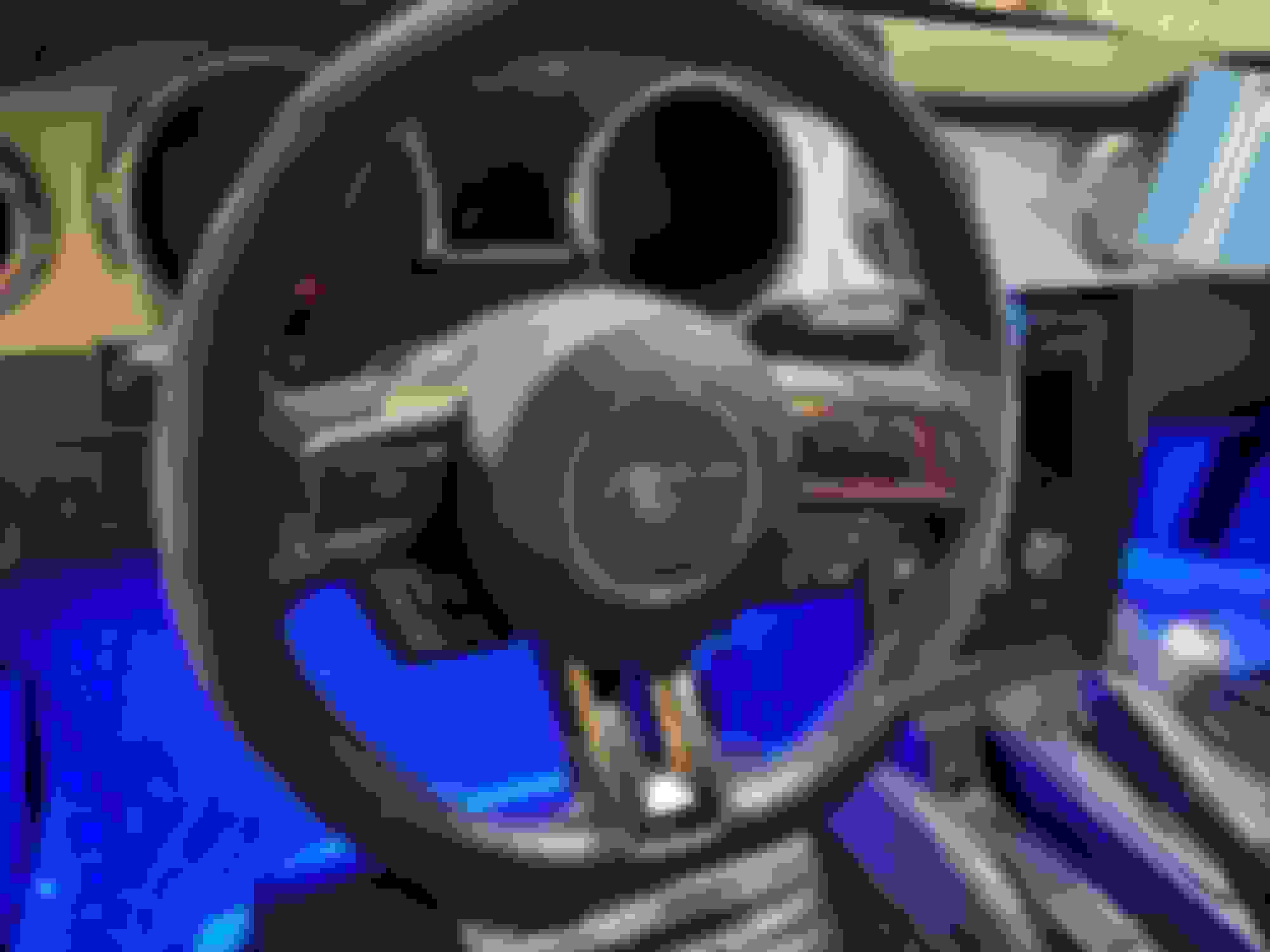
Great news! I got the steering wheel connected and it is working!
Some lessons learned and things to do leftover:
- left buttons and right buttons seem to have a very close resistive value so both sides do the same thing. They will need to go on a different SWC channel instead of how the harness has them joined to the blue line OR add a resistor in front of the left buttons to change the value slightly
- cruise control buttons don't work just yet. I have a plan for those that involves the old button boards from an 05-09 connected directly to each button of the CC side
- phone buttons work, kinda. Seems like phone up and phone down have the same value as the other two (channel 3) so I will need to add another resistor there as well
- airbag connectors - I took apart the connectors from a newer clock spring, and was able to use the wiring from 05-09 by just getting them in the new connectors. No need to cut wires etc
- horn, works as well
- no need to hack the button boards like the posts above
Current wiring setup:
- blue line (channel 1) goes to SWC1
- orange, green and brown go to SWC2
- black, red and purple go to the grown wire on the clockspring (together with the black wire from horn wires)
- white wire from horn goes to the horn wire of clockspring
- yellow goes to backlight on clockspring
I need to order a few resistors and I should have all media buttons working soon! In the meantime... enjoy the picture below! This will go VERY well with the 2014 dashboard that I have in progress with a custom center cluster that uses the 05-09 AC controls, 05-09 gauges with a 2014 lens and indicators and 2014 headlight switches. THAT will be an even more fun of a project!
Last edited by bogdi1988; Oct 26, 2019 at 04:38 PM.


 This will go VERY well with the 2014 dashboard that I have in progress with a custom center cluster that uses the 05-09 AC controls, 05-09 gauges with a 2014 lens and indicators and 2014 headlight switches. THAT will be an even more fun of a project!