When you click on links to various merchants on this site and make a purchase, this can result in this site earning a commission. Affiliate programs and affiliations include, but are not limited to, the eBay Partner Network.
Well since I am sitting at work today and haven't done a thing in the last 2 hours I figured I might as well do something fun and time consuming and show everyone here my car
This is my car, a 2012 Boss 302 Laguna Seca #MP0034. I ended up taking a train down to the SC/GA to O.C. Welch Ford and drove it the 13 hours back to New York back in July of 2013. I have to say that the people there were super nice!
When I got it home I took some pictures the next day.
I have come to find out that my car is 1 out of 44 MP Boss 302 built. Out of those 44 it is 1 of 13 MP Laguna Seca's that were built and only 1 of 9 that were released by Ford for sale. My car was ordered on 9/30/2010 by J. Collins to be used for Prod Plan-Stylg for Ford Motor Company which ranged from Body Engineering, Chassis Engineering, Powertrain Engineering, etc. so I would have to try and find out which department J. Collins worked in in 2010 to find out what department the car was used in. It has a production date of 12/13/2010 build date of 12/30/2010 and was apparently had a ship to destination of Diversified Service Tech in Romulus, MI.
Anyway, as I got back to New York at around 2 in the morning I believe, the first thing I did was grab my ramps and some tools and went down to work where I could use the lights to see what I was doing. First thing I did was check to see if the side pipe plates were removed and wouldn't you know it they were! No wonder it sounded so glorious on the entire way up!
Quick sidenote, the drive up was amazing! Lots of people staring at the car and taking pictures as I was driving by them. Even had a Camaro and Challenger try to race me haha.
Next thing I did was make my way to the back of the car and removed the factory mufflers and put on some Ford Racing SVT Sport mufflers. I have to say that the SVT Sports have a slightly deeper tone than the regular Ford Racing Sport mufflers (think 11-12 GT500 mufflers vs. 13-14 GT500 mufflers difference) and they are absolutely fantastic! Zero drone whatsoever, fairly quiet around town and they just bark when you step on it! I have gotten quite a few compliments on the sound of the car. Unfortunately I have no sound clips of the car with the muffers and the side pipes and these mufflers don't seem to be very popular on GT's.
My next modification came in the way of a Peterson Oil Can which deleted the PCV system. I ended up ordering a kit from Scott on Boss Mustangs Online as he made a bracket and provided the PCV fitting and hoses. With the bracket I didn't have to drill into the firewall which was really nice and a big factor in getting this system. I didn't like the JLT catch cans as at the time Jay was still having to replace the plastic pieces with the brass fittings and I wasn't a huge fan on his refusal to redesign the CAI to properly fit the Boss Manifold when it was released. So this is what it looked like with the Peterson can on there back in January of 2014.
The next mod I did was to get a tune from Hypermotive back in March or April of 2014. Well this was by far the absolute worst mod I did. First, I found out that I have a one off ECU code that no one had seen before. Jason wanted me to try and load the SCT tune that came on the X3 and if they did he would send send me the Hypermotive tunes for my car. I figured whoever this "unnamed tuner" was they should have been able to tune a stock Boss 302 and Jason was even running this person's tun on his car without issues so I figured it would be good enough .....
Well I loaded up the tune and within a few days maybe a week or so I had the car go into limp mode and had a code pop up. So I pulled the code and it was a misfire issue if I am recalling correctly. Let my long list of issues begin with this one problem. I emailed Jason and told him what happened and asked him if I should datalog for him and he said yes please (well not exactly those words but that was basically what the email consisted of) and sent me file with the parameters his tuner wanted me to log. Well the file was tagged Mike Wilson so I knew at that point who this mystery tuner was a few months before the "forum ****storm" occurred. Anyway, having never dataloged before I selected the parameters and sent a ridiculously long file for each thing Mike needed, but I never got any answer from Mike or Jason so I went along my way and did some research. Over the next 6 months I kept running into random misfire codes, camshaft position sensor codes, camshaft actuator codes, phanton CEL's that would come and go as they please with no trace of them and a car that would run like a raped ape or like it was dragging an anchor until 3500 RPM and then launch like a space ship. I changed out a whole bunch of sensors and swapped coil packs to no avail. I ended up finding out that a lot of the early production Boss cars had bad wiring harnesses that would end up destroying itself so I think that was my main issue although I will never know, but everything started after I loaded a tune into the car which is why I consider it the worst mod I did. Oh well, **** happens I guess, just have to take things in stride.
That being said I went out and got a set of Kooks side pipes as I heard nothing but amazing things about them. This was my favorite mod . If I thought I had gotten a lot of compliments about my old exhaust setup well this one blew it out of the water. I even had the driver from Con-Way who delivers to my job say something about it. Apparently he leaves near me and I have to drive by his house on the way home and he absolutely loved the way the car sounded and he insisted that I did headers or an O/R pipe or something. If you are looking to just increase the noise of the car without effecting drone or anything like that this setup was amazing. At WOT it was like a NASCAR car screaming just amazing and at 7500-8000 RPM it was like angels singing, just amazing! Here are a few sound clips I have of the car from my Instagram page in case you are curious.
I also grabbed a set of BMR LCA's and UCA w/mount to try and help cure the wheel hop that I was having but the UCA required me to remove the rear seat delete trays in order to get to the bolt and without the replacement hardware I didn't want to go and do that so I just put the LCA's in for the time being. The wheel hop was almost all but eliminated when I did this and you could launch the car without the rear end just staying planted which was really really nice for a change so I never felt the need to go after the UCA until I started doing some real mods.
I had my helper Duke inspecting the LCA's
This is how Men color coordinate haha
At the same time I also decided to clean up the rear end. When I bought it, it had this weird emblem on the back of it so I figured it was time to remove those as well as tint the rear candy cane taillights as I hated these!
It was also time for some new tires! When I picked the car up the tires weren't all there and after driving the car through the winter when there was no snow on the ground and a few more months during the spring and summer they were done for so I said my good bye to them in classic style before I welcomed the MPSS tires
Anyway, I was coming home from work when I heard a loud tapping sound. I was sitting at a red light and as soon as the light turned green that was when I heard it. To make matters worse it was my birthday . That weekend I took a video of it since I was hoping that it was just the A/C compressor stretchy belt even though I was almost positive it was Rod Knock.
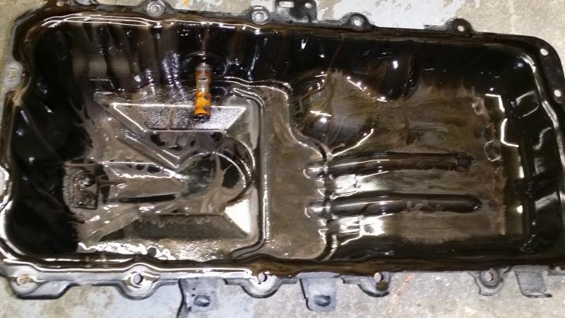
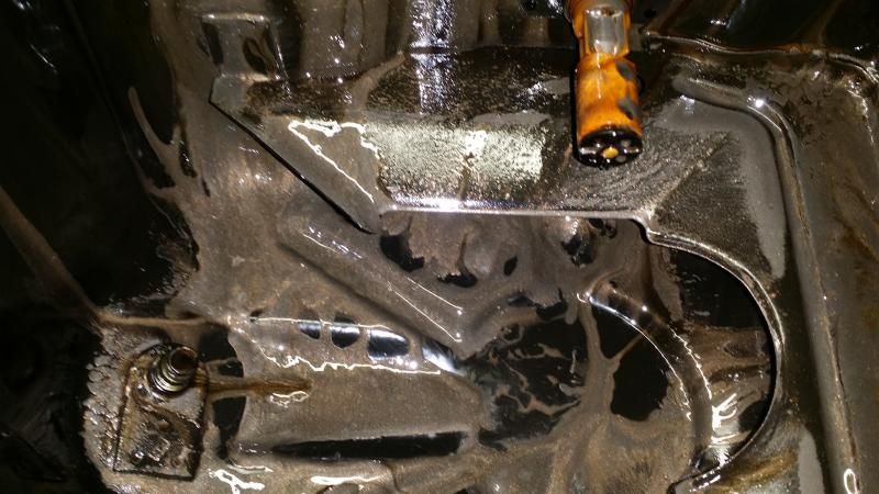
I ended up draining the oil to see what it looked like and to confirm if it was indeed rod knock. Upon first inspection I thought I was in the clear. I didn't see or feel any pieces of bearing in the oil even as I was draining it using a scolobast until I got to about 7 quarts of oil put into empty oil jugs when I started noticing metal flakes in the bottom of the pan. These pictures were after about 8 quarts were removed I believe.
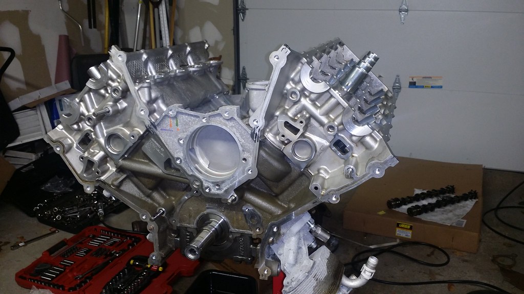
Well after owning the car for a year and 1 month and only being able to enjoy it for roughly 7 months before some issues arrived it was time to pull the engine out of the car. It took me about 8 hours to pull the engine due to having to fight with the transmission to separate from the engine for about 2 hours or so. I have a writeup on removing the engine on another forum if anyone is curious about it I can put it here as well, but here are some pictures during the removal of the engine.
The obligatory sort empty engine bay picture
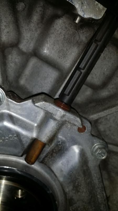
Now that the engine was out of the car it was time to bolt it up to the stand. I removed the flywheel, clutch assembly, and pulse ring so that I can bolt it to the engine stand. Upon doing so, I noticed that it looks like I didn�t have the revised o-ring around the crankshaft position sensor like I was told since it appears I have the stock orange o-ring. At least this confirmed my suspicions about possibly having a bad crankshaft position sensor after I performed a quick test.
As a quick aside, I know that for the Boss 302 this should tell you if the CKP is bad or not. I�m not sure if it is the same for the GT�s but I would imagine that it would still hold true. I am 95% sure that this is the way you do this but I will look around a bit more and see if I can�t find the thread and update the post in case I am wrong. Drive the car for about 15 or 20 minutes in 4th gear with the RPM�s between 4,000-4,250 and the check engine should come on and flashing. If this happens, than everytime the solution has been to replace the CKP. This is normally a problem for the 2012�s as they revised and udated the wiring harness for the 2013�s. It seems that the wiring prongs act as tuning forks almost and vibrate themselves to death on a road course in a matter of 15 hours or so.
Pressure Plate/Clutch Assembly � 9 x 13mm
Flywheel � 8 x 19mm
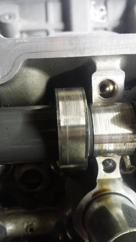
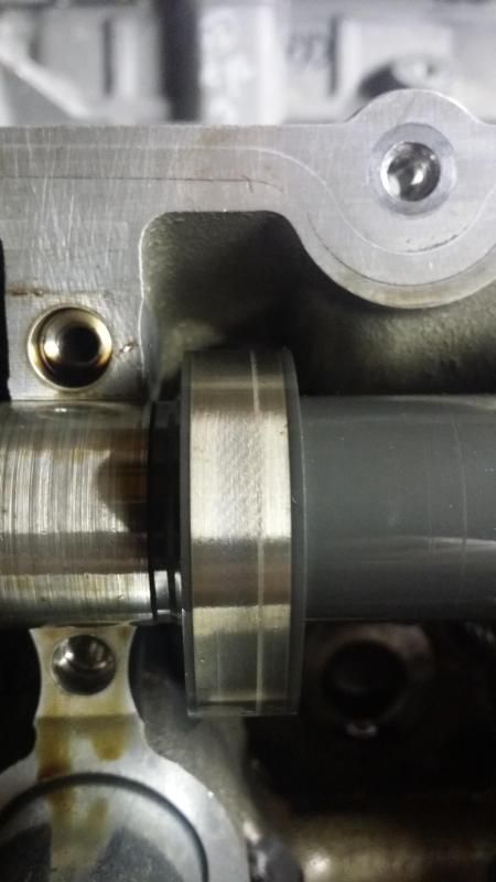
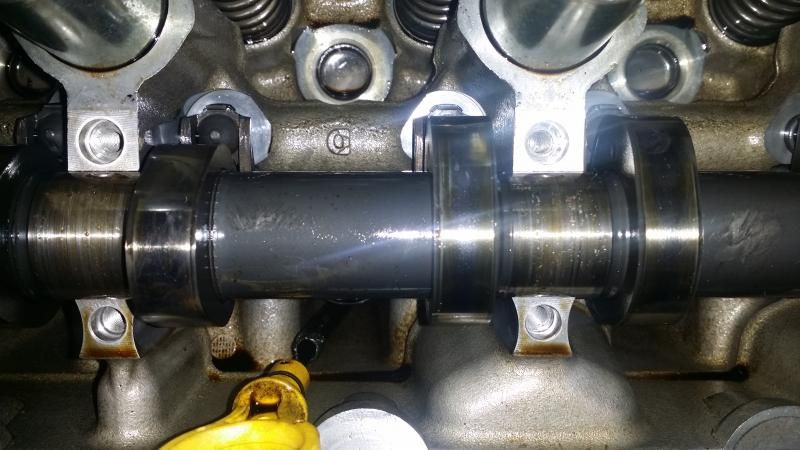
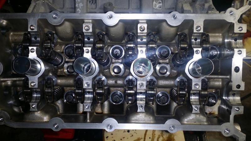
Once I got everything removed I was able to bolt the engine onto the stand and remove the hoist from the garage. From there I pulled the motor mounts off followed by the valve covers to see if there was any carnage in the valvetrain. I couldn�t really find anything outside of some metal shavings on the shaft of the uhhhh camshaft as well as some odd wearing on two of the LH intake cam lobes. Outside of that everything else looks ok by my eyes (ie. No giant chunks of pieces missing or gouged).
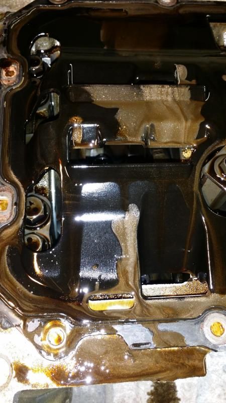
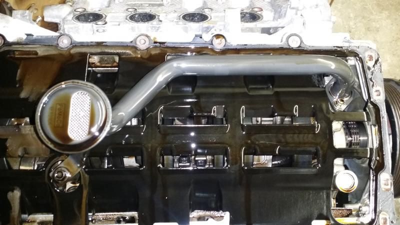
From there I turned my focus onto the oil pan. I removed the oil pan and separated it from the windage tray (I just grabbed my plastic fastner removal tool and used that to separate the oil pan and windage tray this way I could remove the pan, then unbolt the pickup tube and take off the windage tray). Upon doing so it looked like someone poured silver metallic paint into the oil pan and mixed in a tiny bit of oil in there. After looking at it a bit further, the oil has a bit of a milk shake look to it but maybe I am wrong here so maybe someone more knowledgeable than I can say the oil looks a bit odd like a head gasket leak. So far it has only looked like this when I took off the oil pan so maybe that had something to do with it, but either way I think I can repaint my Vapor Silver V6 with what is in the bottom of the oil pan haha.
Valve Covers - 14 each side (28 total) x 10mm
Oil Pan/Windage Tray �16 x 10mm & 3 x 13mm
Oil pickup tube bolts � 3 x 10mm
Oil Pickup tube spacer � 1 x 17mm
From there it was just a matter of taking everything apart to see if I can figure out where all of this metal was coming from. I started by removing as much as I could off of the block before opening up the front cover.
Just a little note for the Newbies that haven�t done anything like this before (such as me), if you haven�t taken off a water pump before you can grab a hammer and lightly tap the snout to help loosen it up and you should be able to wrestle it out once you can get it to wiggle a little bit. I folded up a rag a couple of times as not to damage the water pump and gave it a little tappy tap tap like in Happy Gilmore.
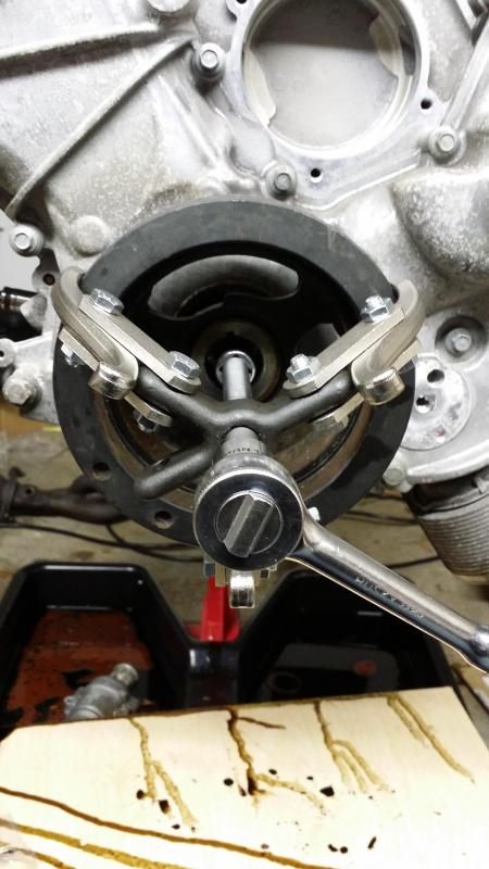
I have to give a big thank you to Tad over at Freedom Racing! I went out and bought a 3 jaw puller to remove the crankshaft pulley. Well, I put it together and the bolts weren�t really long enough for the nuts to get a good grab on them so the second I put some pressure on it to remove the pulley, the ****ing thing exploded and I mean exploded. I think I still have an imprint mark on my forehead from one of the projectiles (nuts and bolts and stuff) hitting my head. I think a squirrel that was watching me work got knocked off the rafter of the garage, cursed at me for being cheap and scurried away. Anyway, I sent him a PM Sunday afternoon about getting me a new 3 jaw puller. I got a PM from him shortly after that saying that he would head down to the office and check for me how soon I could get one. Sunday night he PM�d me back and I ordered it and I had it on my doorstep Tuesday Morning. If you need any Ford Specific Tools I would HIGHLY recommend giving him a shout. This isn�t my first dealing with Tad and every time I have spoken with him or bought something from him you would get excellent service. Automotive Specialty Tools
Anyway, if you have never used a 3 jaw puller on a crankshaft pulley before it is pretty straight forward. There are 3 jaws that connect to either the 3 inside prongs of the pulley or along the outside of the pulley. I grabbed a 1� reducer and put it into the threaded insert for the crank pulley bolt and started cranking. Once it got to a certain point the crank pulley popped right off. It�s nice when you have the right tools to do the job for once haha. Anyway, it looked a little something like this. I realize that this is n't the correct way to remove it as the jaws are supposed to go onto the 3 ribs inside the balancer and you are supposed to pull it off from there. Considering I was planning on replacing the balancer as well as the front seal I figured I would pull it off this was as the crank puller wouldn't properly fit onto those 3 pieces so I wasn't concerned about damaging the factory balancer.
A/C compressor � 3 x 13mm
Alternator � 2 x 15mm & 1 nut x 13mm
Camshaft Position Sensors � 4 x 8mm black=intake; grey=exhaust
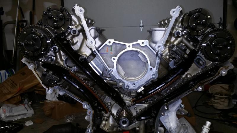
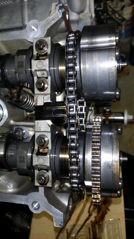
At this point it was time to start breaking into the engine and seeing what is going on in there. So I started removing the front cover. I took the RTV off by hand and grabbed the front cover at the top and pulled it off. Off comes the front cover and I started working on removing the timing chains.
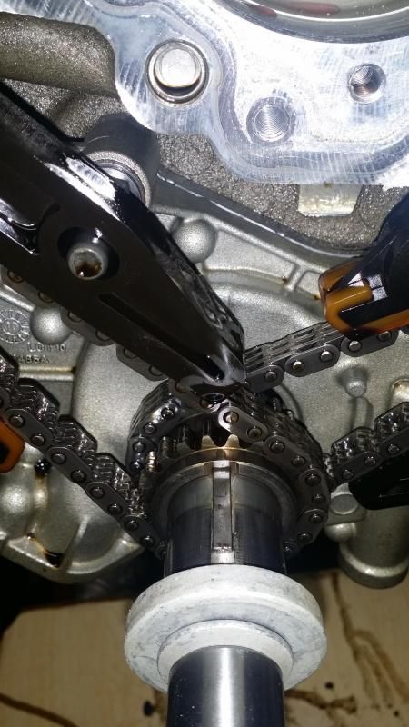
I started with the LH side. First you rotate the crank until the keyway is at the 12 o�clock position and all 4 data matrix�s on the cams are facing up. From there you can remove the tensioner. Remember that the tensioner is still under pressure so I loosened both bolts and held the back of the tensioner and after removing the last bolt I was able to slowly remove it without it having fly off and smack me in the head. When I removed the tensioner I found little bits of metal on the plunger as well as the timing chain guides.
Keyway at the 12 O�clock position
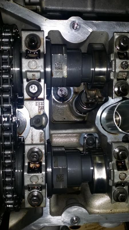
Data Matrix on the top of the camshafts. All 4 have to be facing up. If they all aren�t facing up turn the crankshaft until the keyway is at the 12 o�clock position and all 4 are facing up.
From there you can remove the tensioner arms. You might have to rotate the crankshaft to release a little bit more tension in the chain so you can remove the timing chain guides. After that remove the 6 screws holding the phasers on and you can slide the phasers forward 2 inches. Make sure you depress the secondary tensioner and rotate it 90 degrees this way you can remove the phasers.
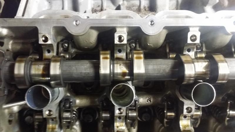
After that you can remove the secondary chain. The procedure is basically the same for removing the RH timing chains except this time you turn the keyway to the 9 o�clock position. After the primary and secondary timing chains are removed, I slid off the crank sprocket followed by the oil pump. Then I went back up top and started removing the cams. The workshop manual is very clear about this since they say it a couple of times and have it written in bold. You have to remove the front camshaft bearing mega cap first or else you could damage the engine. Considering how good I am at damaging the engine just by starting and driving it I figured if I didn�t do this first I would end up cracking it in half somehow so what the hell. After that I slowly started loosening the bolts 1 turn per bolt for the rest of the cam caps following the torqueing sequence this way I could remove whatever spring pressure was on the cams evenly. After removing the front mega cap I found some pretty bad scoring on the cam journals and once again I found some pretty big metal flakes on the camshafts. After removing all the cam caps I was able to pull the cams out and found scoring on almost all 32 journals. They are deep enough where you can feel them through the glove and your fingernail catches on them. I�m not certain how bad that is but that will be addressed later after talking to some people about the build plans. Anyway, onto more pictures.
Some pictures of the metal pieces on the cams:
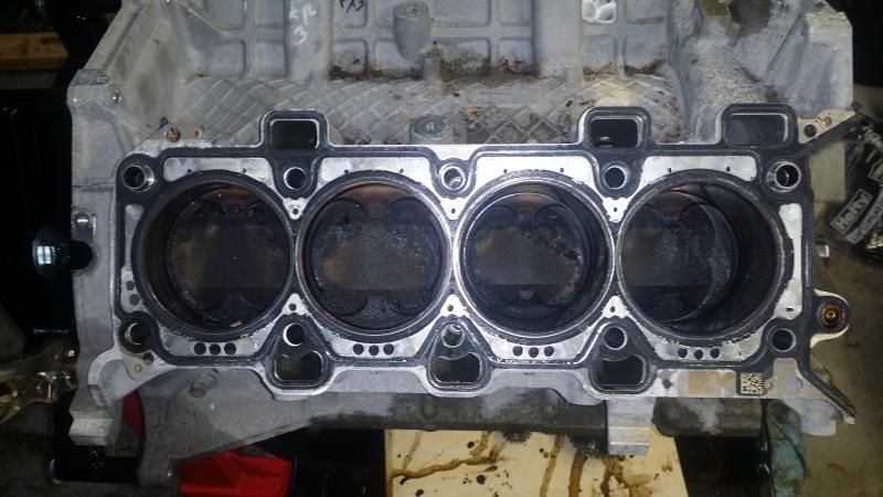
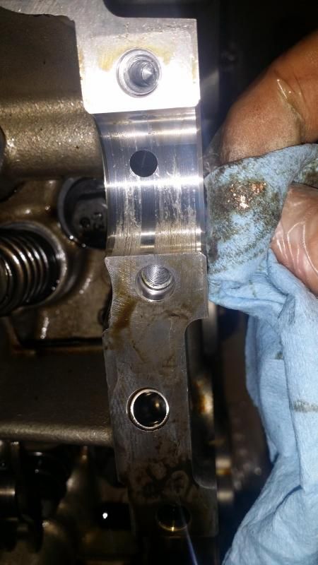
After that I removed the crankshaft position sensor and the cylinder head temperature sensor. I cleaned up the heads a little bit and took the picture-o-shinyness
Cam Cap Bolts � 20 each side (40 total) x 10mm
Cylinder Head Temperature Sensor � 1 x ��
Front Cover � 8 x 10mm / 7 x 13mm
Oil Pump � 2 x 8mm / 1 x 9mm / 1 x 13mm
Phasers � 3 per phaser (12 total) x 10mm
Timing chain Guides � 1 each side (2 total) x 10mm
Timing Chain Tensioners � 2 each side(4 total) x 10mm
Wow. Great thread here Sean. Killer car for sure.
What caused the damage? Was it the tune or just a failure?
Thanks Tony, more to come!!
I think it was an oiling issue. Looking at the marks on the rods and the crank journals along with bearings everything points to oil starvation which is odd considering I pulled out all 8.5 quarts of oil. I'm not sure what happened to be honest. I did notice the oil pressure drop ~2 psi on the oil pressure gauge a couple of weeks before hand but I never thought anything of it in all honesty. I doubt the tune had anything to do with it but I did have a couple of knowledgeable people telling me that knock can cause spun bearings if it is severe enough and to pull the wrist pins to see if they showed any signs of knock but I never did get around to it especially since it was a moot point at that time IMO.
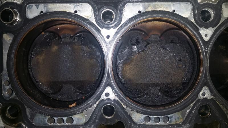
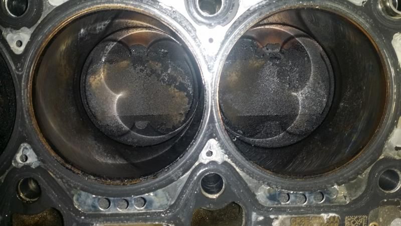
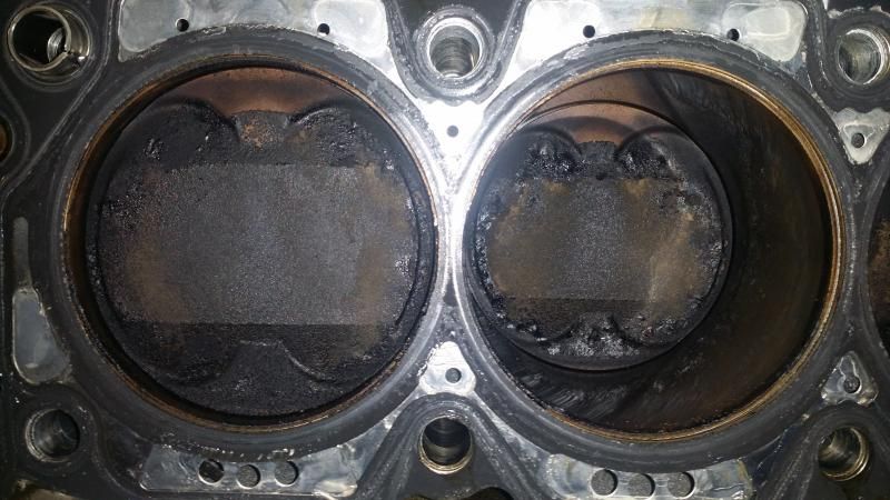
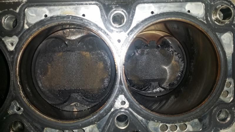
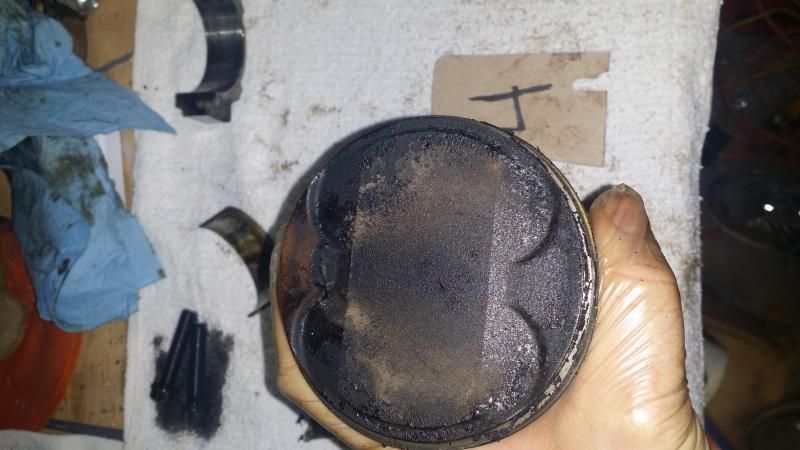
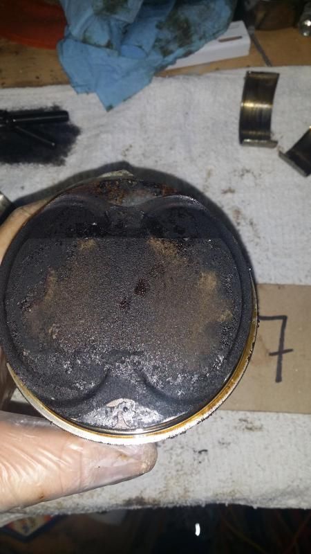
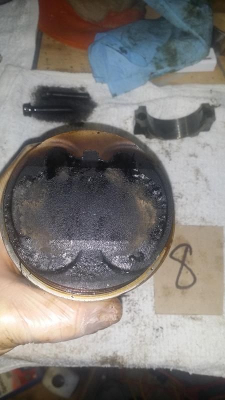
Here is the LH side Heads along with a close up of the piston heads.
Here is the RH side heads along with a close up of each pistons.
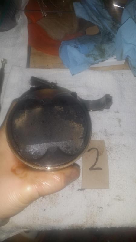
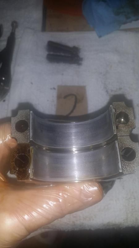
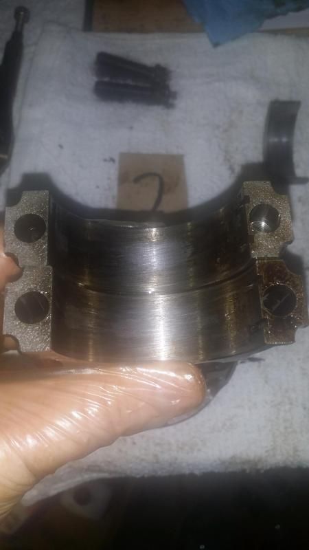
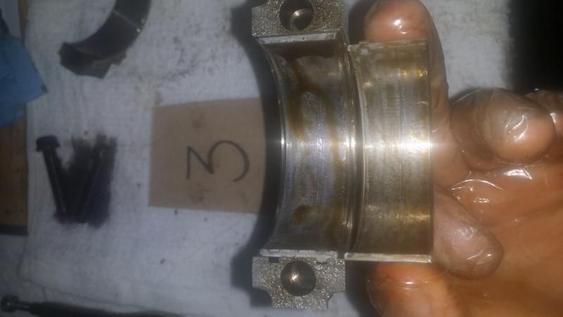
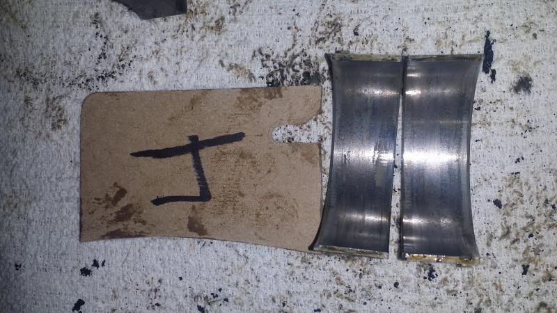
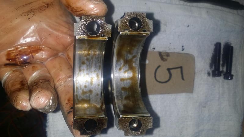
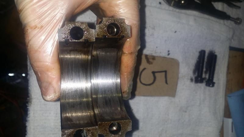
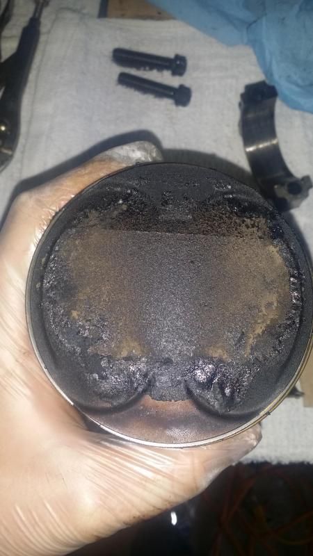
After I pulled the heads off it was time to go ahead and take out the pistons. I turned the engine upside down and started getting to work on the pistons. Upon removing the 1st piston the bearings sort of stayed on the crankshaft. By the end of it 5 out of 8 pistons had the bearings stay on the crankshaft while the others came out with the pistons caps. Now, I am not 100% certain if that is indicative of spun bearing but I figured I would at least mention it in case that would be a sign of a spun bearing. All of the rod journal caps had some scoring marks on them with what looks like a hot spot while some of the piston bearings had some marks on them. Anyway, onto the pictures. There are a lot of them so my apologies in advanced.
#1
#2
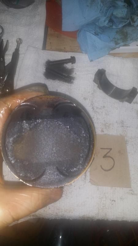
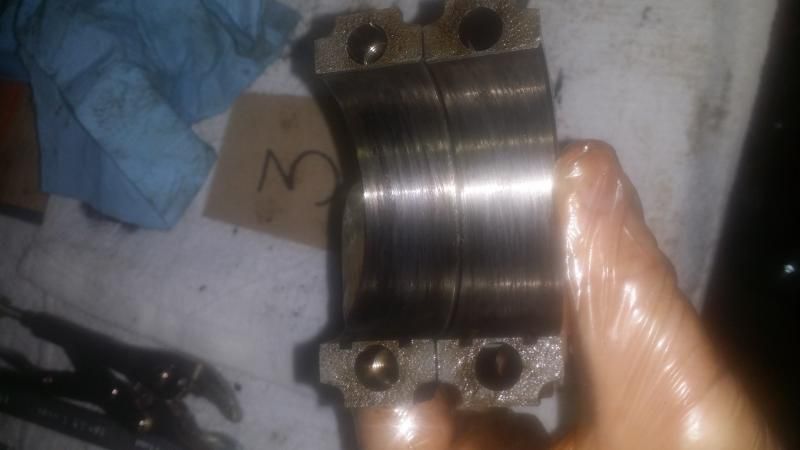
#3
#4
The bearings on number 4 looked like it had the little tabs worn down a little bit and the stamped part numbers on the bearings seemed to be a little bit worn down.
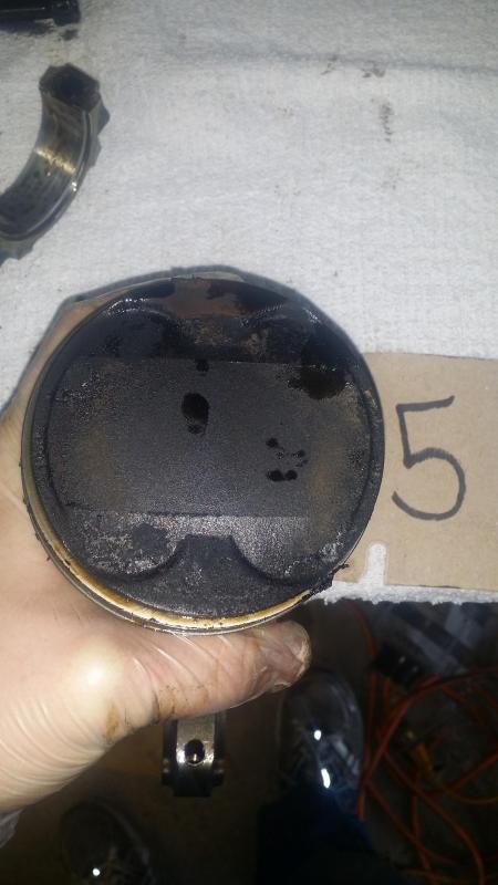
#5
#6
You can sort of see it in the picture but it looks like some of the metal found in the engine came from #6 due to the fresh scoring on the lower part of it
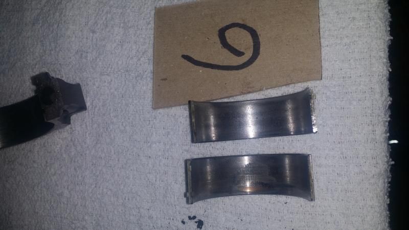
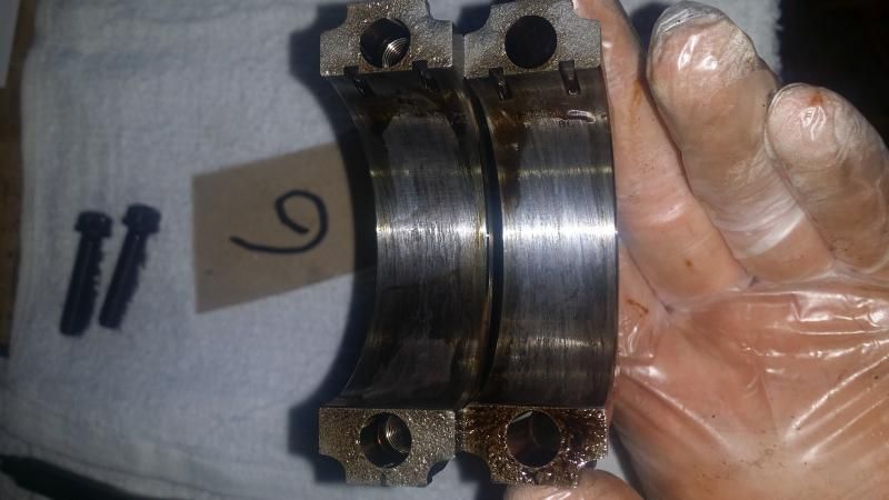
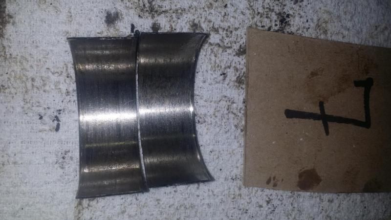
#7
The bearings on #7 were completely destroyed! It was out of round, the edges were ground down to an point basically. The little tabs were worn down to almost nothing and the stamped markings on the back were completely worn away. It is sort of hard to see in the last picture but you can almost see where those tabs are on the bearing and they are almost completely gone.
#8
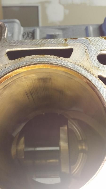
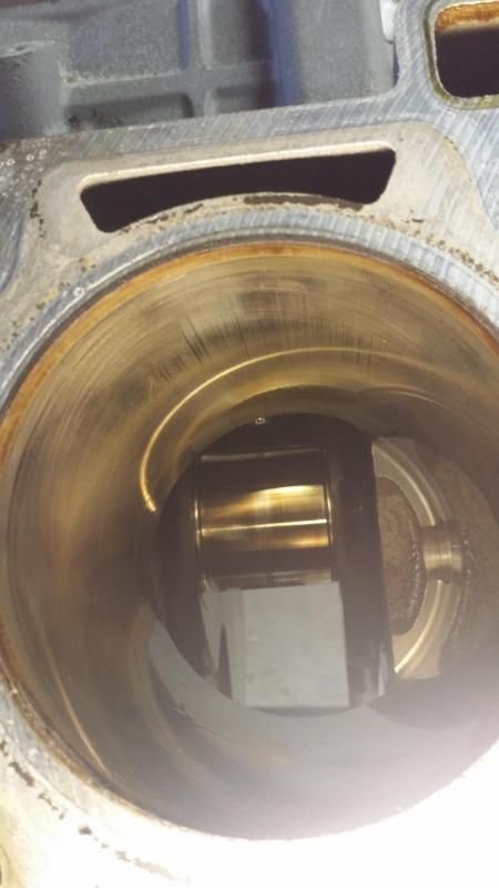
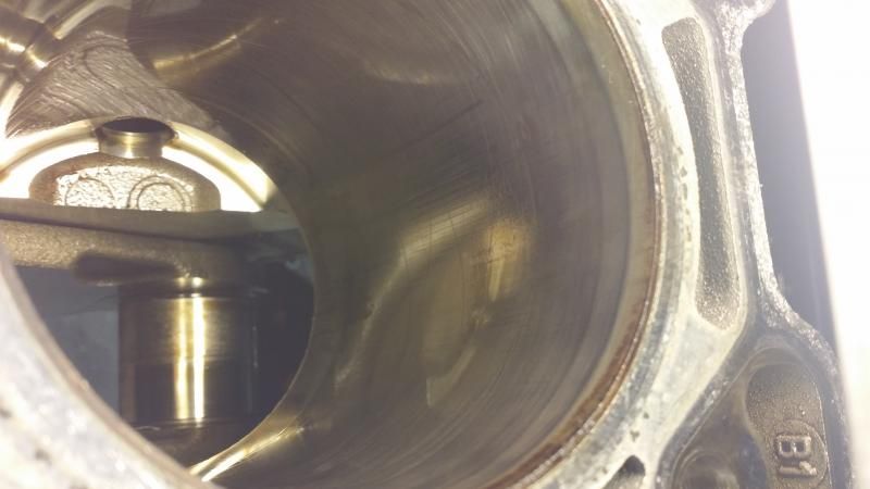
Outside of that I looked at the cylinder bores and they looked like they were in fairly good condition. Just some light marks on 2 of the bores along with one bore that had vertical marks along with some sort of cross hashing marks.
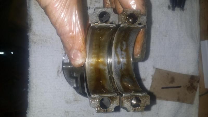
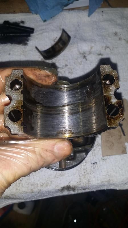
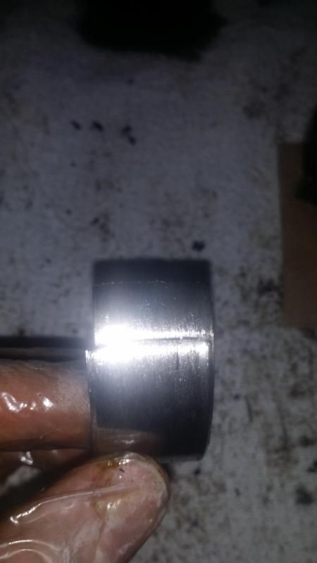
You can see in this pic how one side of the crankshaft is shiny and the other side is dull ... Well dull is bad. The dull side is the side with #7 rod bearing that was chewed to ****e
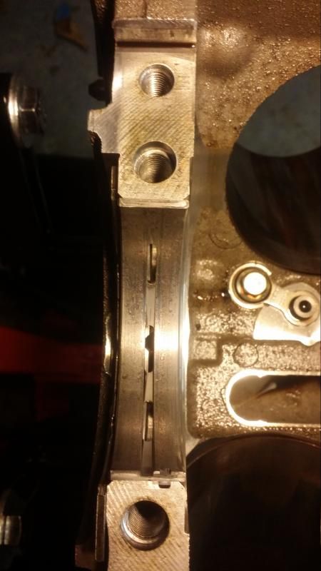
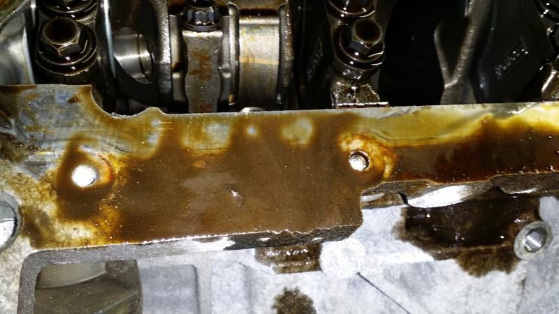
After that I went to go and take out the Main caps out and the first one came out super easy. The 2nd and 3rd ones I pulled out with my hands. In my infinite wisdom I bolted up the block to the engine stand without removing the rear main seal and crankshaft rear seal plate. I couldn�t finish taking off the last main cap because the 2 15mm bolts in the center are being impeded by the plate so I put the other 4 back on so that I didn�t lose anything.
Boss 302 Head Bolts � 10 (20 each side) x 15mm
Boss 302 Oil Cooler � 3 x 10mm / 1 fitting 14mm or 9/16
These were a dirty pirate hooker to try and take out. I had to use my hands to try and pry them out which was no easy feet. #5 main cap has a special place in hell as it took me about 45 minutes to try and pry it out haha. I found out that most people use a rubber mallet instead of their fingers or they have a pry tool that fits inside of these little spaces and they can pry them off.
Wow. Great read here Sean.
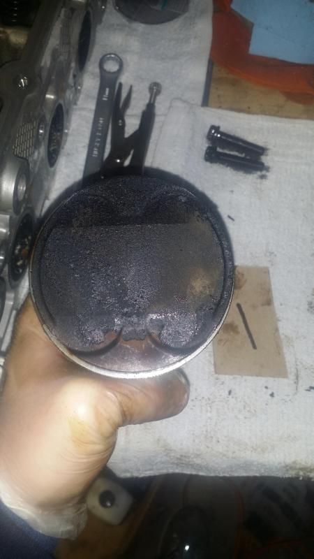
Looking at the piston heads, it looks like there was a build up to it finally giving out. Is that what you're thinking?
Hmmmm I don't think so to be honest. I did think that the buildup was a bit excessive but I don't think it is anything that would have caused a major issue.
Originally Posted by PJRManagement
Thanks for posting, especially the pics. Love your LS. I hope you nurse her back to health soon.
Thanks, I hope so too! It has been a while since I got it up and running so I am looking forward to it.
Originally Posted by 5.M0NSTER
car looks wonderful. Hope the 5.4L works wonders for your ride!
Thanks, me too! If I can get 560 on pump gas and 580 on E85 I would be ecstatic!
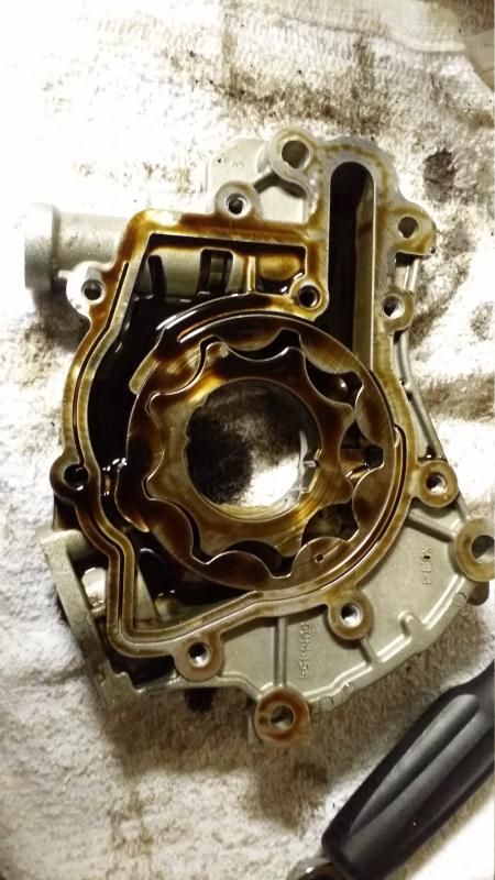
I turned my attention to the oil pump and after removing all the screws for the oil pump I opened her up hoping to find it shattered or cracked but as usual I was let down here. Here is what it looked like when I opened it up.
After taking a good look at it I didn�t see any cracks or anything like that but I did notice what we now know is bearing material on the inner and outer gears of the oil pump. I don�t see any scratches, cracks, gouges, brakes etc. in the oil pump gears so they should be good even though they will be being replaced in the build with a set of TSS gears.
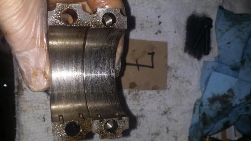
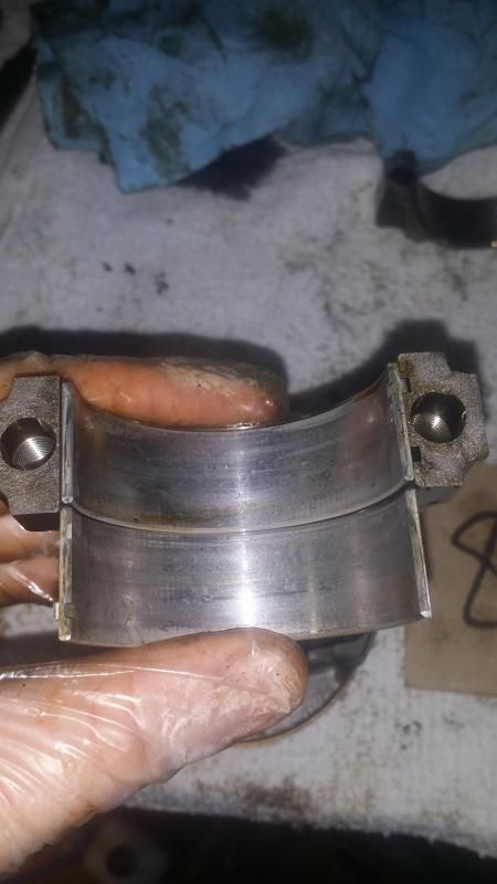
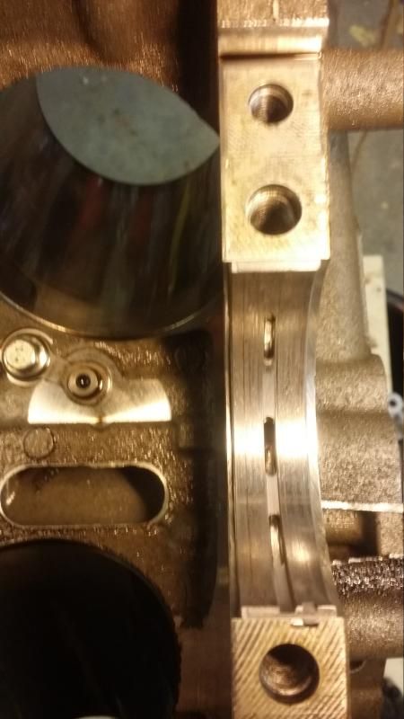
Once I gained my strength back I decided to finish off tearing the block down to nothing, so I got to work on pulling the last 2 caps out. #4 came out fairly smooth (about 5 minutes of back and forth while pulling up at the same time) while #5 was decidedly more stubborn. In all honesty I felt like blowing it out with some C4 since it seemed to be coming out 1/16th of an inch every 4 minutes. After quite some time and wrestling, out it came and I was able to take a look at the crank. I didn�t notice any odd or unusual marks outside of what appears to be some marks from when the crankshaft was balanced so I didn�t take any pictures. But if you guys want pictures of my shaft you will have to get in line.
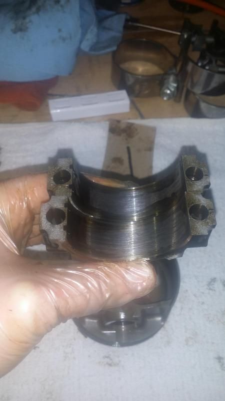
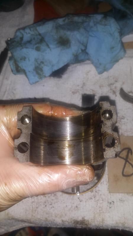
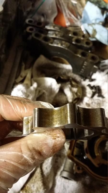
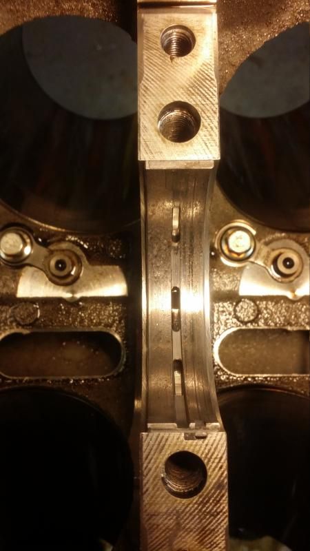
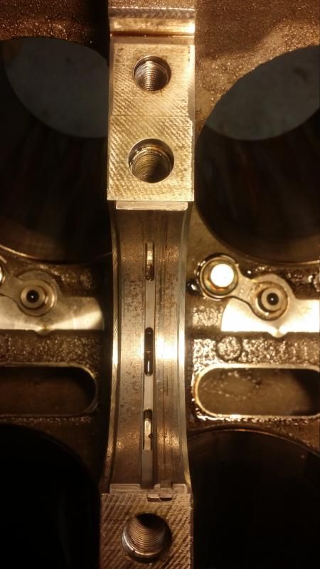
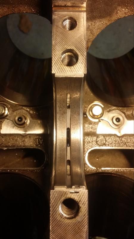
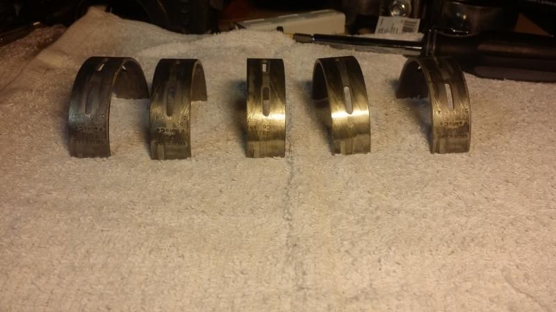
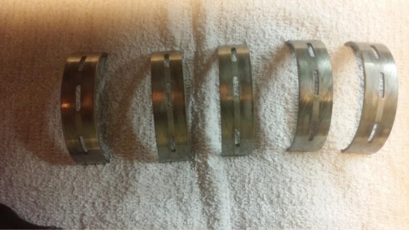
Anyway, I pulled out the bearings and from the top they looked decent, some minor scoring on them but the bottom side looked like there were some wear marks on them.
I tried to get a picture of all of them together to save some space but you can see for yourself. #3 & #4 both had the part numbers wiped out from them and it looks like the little tab was being worn down as well. All of the caps had these weird spots on the bottom that were completely smooth as opposed to this criss-cross pattern that seems to be made that way. If you look at the overhead view you can somewhat make out what I am talking about especially looking at the right hand side of the #3 bearing (order goes left to right so #1 on the far left and #5 on the far right).
Outside of that the block is completely torn down with nothing left on it.
I figured with such a long and somewhat boring read a little humor was in order haha.
In November of 2014 I knew which direction I was heading but didn't know the specifics of it although I did get some things during the Black Friday sales.
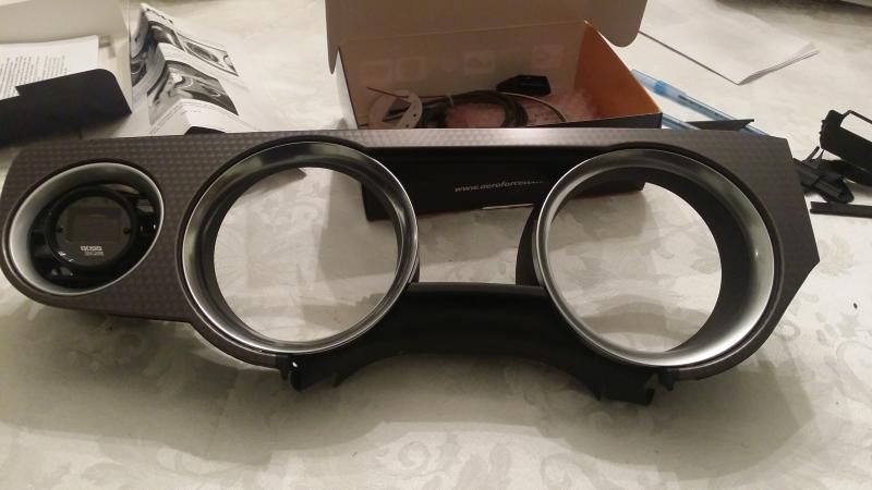
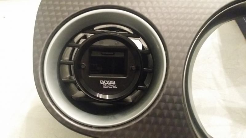
I got sorta bored just doing nothing so I went out and grabbed the Gauge bezel off of the car so I can put in the Roush vent pod and drop in the Aeroforce gauge to see what it looks like.
I was trying to keep it somewhat sleeper where if you weren�t looking for it you wouldn�t really notice it in there. I may take the black gauge face that came with it and remove the Aeroforce logo and put a Red Boss 302 logo in that one and see what it looks like.
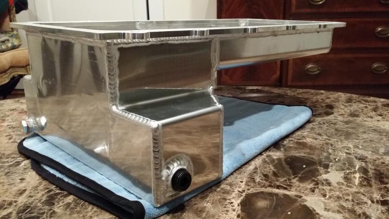
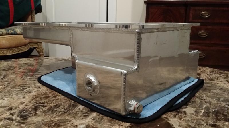
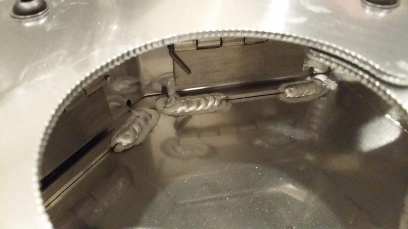
Here are some pics of the Moroso Race Pan since it is such a work of art. I have seen a lot of Boss 302 guys running the Moroso Race Pan as well as the Canton unit (In fact that is what Kenny Brown uses on his line of cars). When asking about it I just kept getting the same answer about the Moroso Race Pan. The internal baffling and trap door setup works to keep the oil where it should be and will prevent any oil starvation issues when braking and in mid turn. It also has a bung on it for an oil temperature sensor which is an excellent tool to have for when you are going around the track to keep an eye on things and just a great idea in general. You will need the 5V regulator to run it with the Aeroforce gauge though so don't forget to either buy the one Aeroforce sells or makeone yourself. I just have to figure out which oil temperature sensor to get and get it all wired to the Aeroforce gauge. I believe Aerofroce has one but I will email them after the holiday and see if that is what I should be using.
Around December I started to get things finalized with JPC regarding the build of the shortblock. I will be using a 2013 block in which they will be using the Darton Hat Style Sleeves with an offset ground crank creating approximately 326CI (so much for the 302 in Boss 302 lol). Internals will be custom Diamond Pistons, Total Seal Rings AP finish, Manley Lightweight I beam rods, King HP Series Mains, Clevite Rod Bearings, and ARP Hardware along with Teflon Skirt coating on the Pistons. I will keep the stock compression ratio as I plan to run it on pump gas until I can find a reliable place for E85.
The oil pan looks great! Nice welds. That's the first thing I look at to tell if it's quality or not. The oil gears did look to be in good shape. Were there metal shavings on them as well Sean?
The oil pan looks great! Nice welds. That's the first thing I look at to tell if it's quality or not. The oil gears did look to be in good shape. Were there metal shavings on them as well Sean?
Yes sir, when you look at the picture with the oil on the gears you can see the lighter color dots, those are little bits of bearing material on the gears.
]I got some assembly lube in the mail on Saturday and got to work putting in the TSS Oil Pump gears. While digging through some threads I found a post by Chris (BadPiggy) on S197. On the TSS Oil Pump Gears they have the number for what gears go into which kind of oil pumps as well as a set of numbers on the bottom. Here I thought that they were just a batch number but that doesn�t appear to be the case.
Originally Posted by BadPiggy
Interesting.
Just called TSS.
They place those lot numbers on the rings just before shipping.
They record who received what lot numbers when sent out.
If they catch a bad gear going out...or a gear fails after it's gone out...they know who to contact.
Sounds to me like it's one way for them to lookout for us, the end user.
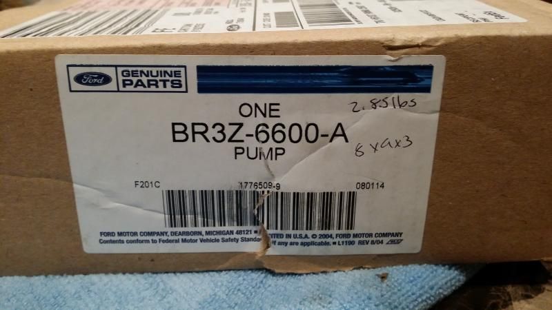
Anyway, onto the pictures I guess. Due to the fact that I have little flakes of metal throughout my entire engine I am going to be replacing most of the internal engine parts. So I hit up Steve over at Tasca and they got me a new Oil Pump.
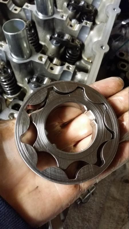
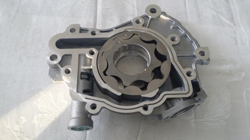
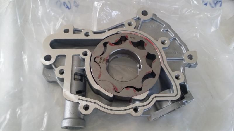
I opened up the oil pump and pulled out the cast oil pump gears and grabbed the Permatex Assembly Lube and coated the news gears in some lube. I oriented them in the same way as the old gears came in. It took a bit of persuasion to get them in as they didn�t just drop in like the stock gears. I put a light coat of assembly lube on the new gears so that the rotating surfaces were red and covered but not too covered where you had these giant globs of lube on the gears. After rotating the gears by hand a couple of times to make sure that the assembly lube worked its way into everything I closed it up and torqued the screws to 90in./lbs. When I tightened up the backing plate I rotated the gears as well to ensure that there were no issues or binding. I forgot to mention to make sure you either buy a new oil pump pickup tube gasket or reuse the old one from the oil pump if you decide to buy a new oil pump.
Old
New
Parts used
TSS Billet Oil Pump Gears (JPC Racing Part #) � 1760
 12/24/15, 02:22 PM


 . Oh well, **** happens I guess, just have to take things in stride.
 . If I thought I had gotten a lot of compliments about my old exhaust setup well this one blew it out of the water. I even had the driver from Con-Way who delivers to my job say something about it. Apparently he leaves near me and I have to drive by his house on the way home and he absolutely loved the way the car sounded and he insisted that I did headers or an O/R pipe or something. If you are looking to just increase the noise of the car without effecting drone or anything like that this setup was amazing. At WOT it was like a NASCAR car screaming just amazing and at 7500-8000 RPM it was like angels singing, just amazing! Here are a few sound clips I have of the car from my Instagram page in case you are curious.


 . That weekend I took a video of it since I was hoping that it was just the A/C compressor stretchy belt even though I was almost positive it was Rod Knock.


 I did notice the oil pressure drop ~2 psi on the oil pressure gauge a couple of weeks before hand but I never thought anything of it in all honesty. I doubt the tune had anything to do with it but I did have a couple of knowledgeable people telling me that knock can cause spun bearings if it is severe enough and to pull the wrist pins to see if they showed any signs of knock but I never did get around to it especially since it was a moot point at that time IMO.