Hellion Twin Turbo Project
 6/11/13, 02:38 PM
#1

Hellion Twin Turbo Project
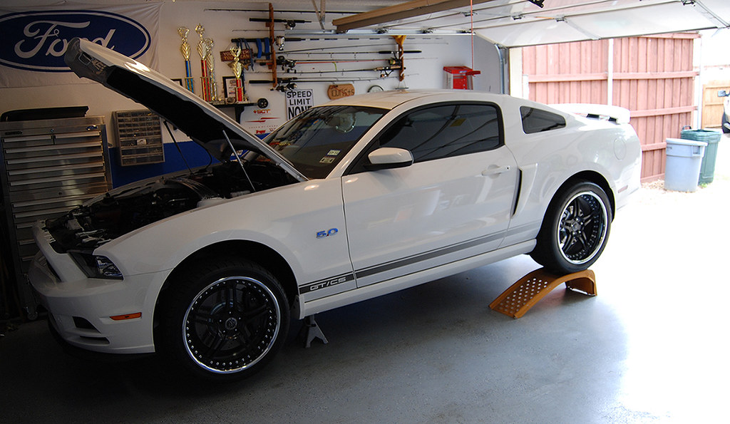
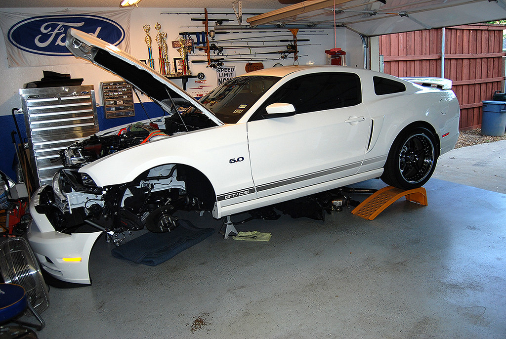
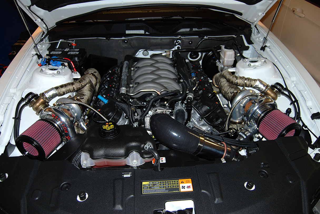
Figured I would share what I have been working on. I am installing a Hellion Twin Turbo Kit on my 2013 A6.
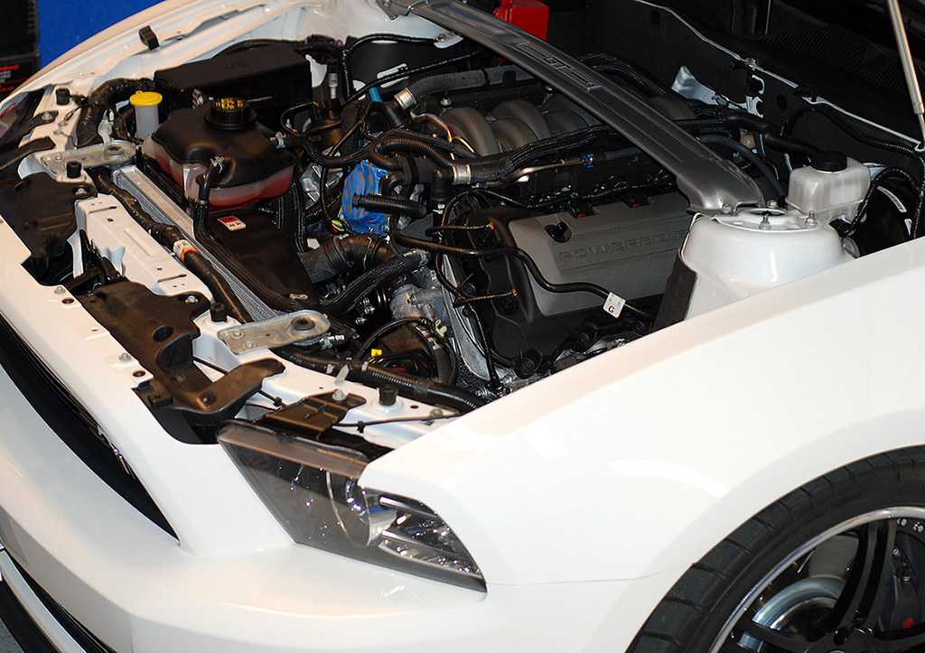
Front clip off.
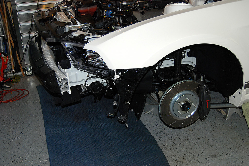
Front suspension removed.
Since I was removing the K-Member, I decided to use the factory strut tower along with some come along straps to help hold the motor. I put them near the ends where it had more support from the towers. Worked perfect!
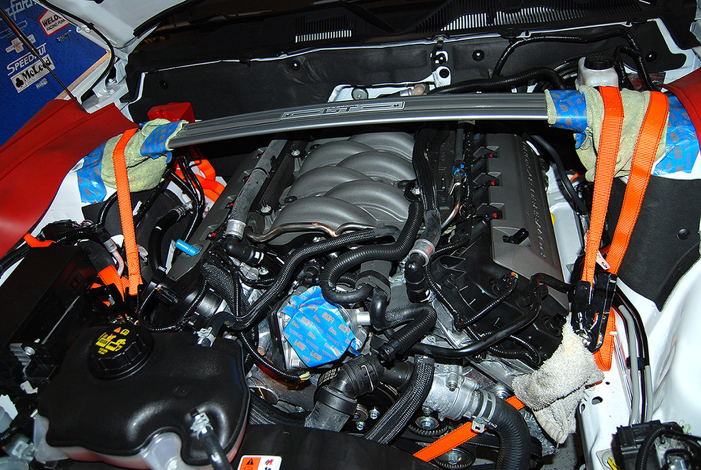
The crank pulley has 3 bars that I used 2 of them to hook to.
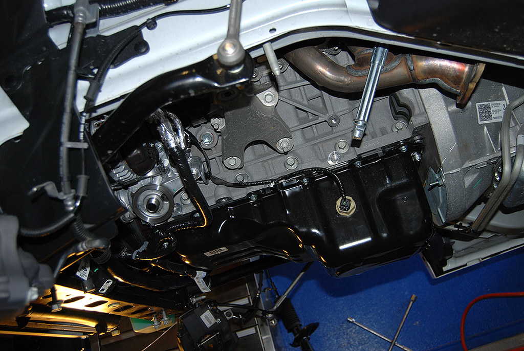
With the engine supported, I unhooked the steering and dropped the K-Member.
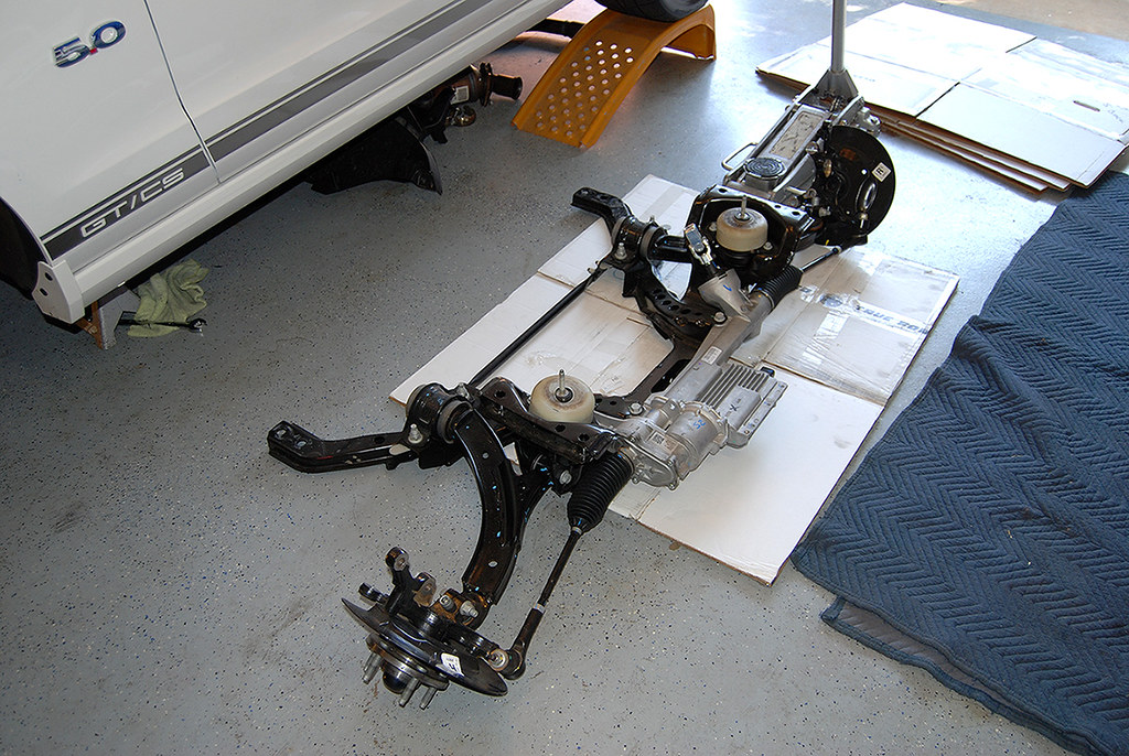
That left room to pull the oil pan off so I can have fittings put in properly without punching holes in it and using the tap. I am not a fan of that technique.
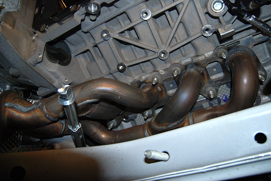
By removing the K-Member and motor mounts, it made it much easier to get to the headers. For the passenger side I had to CAREFULLY coerce the A/C line a little to get to the front bolt. But it went easy enough with little drama.
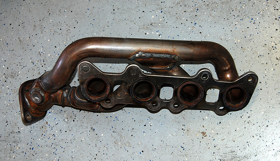
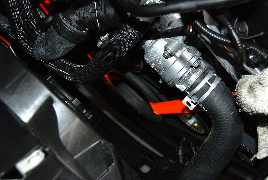
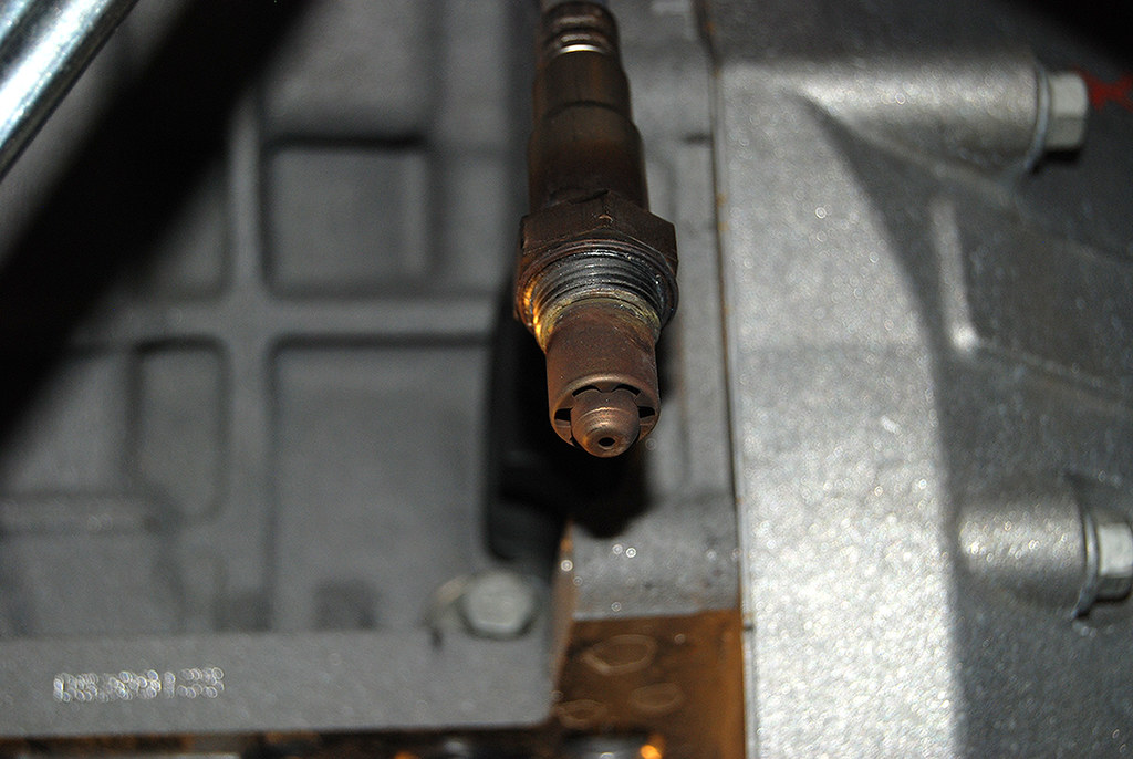
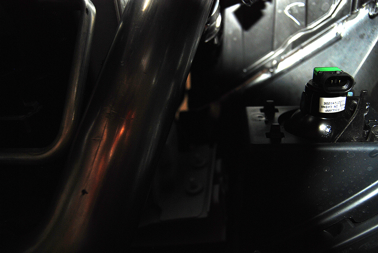
Here's a good shot of the front factory Wideband O2's.
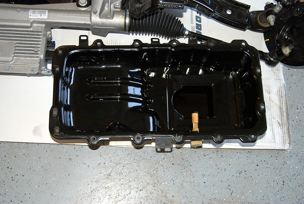
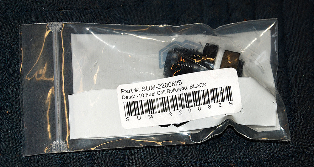
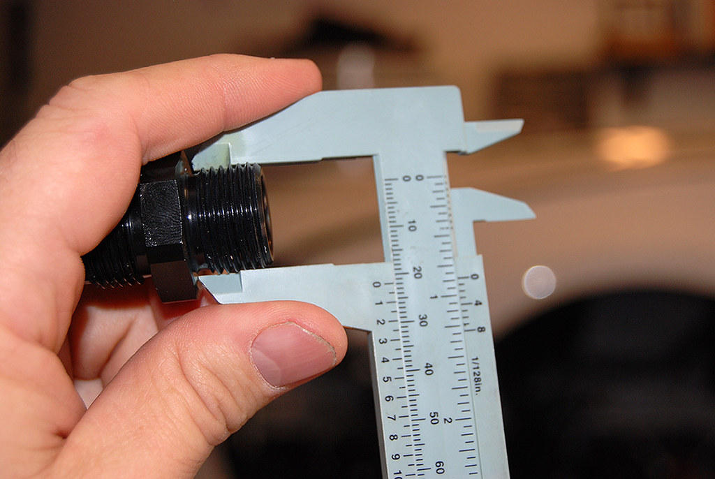
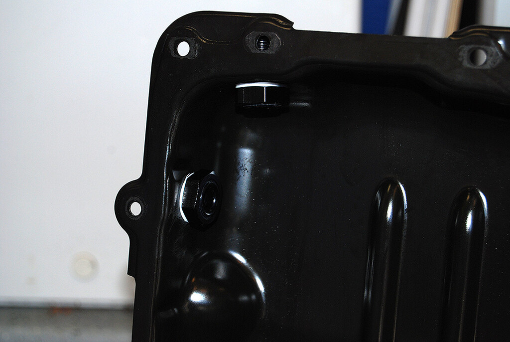
Here are the bulkhead fittings that I am using for the oil drain back.
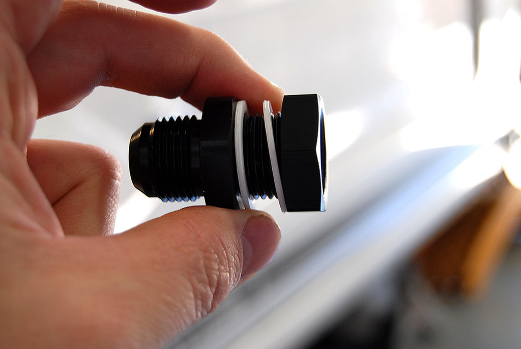
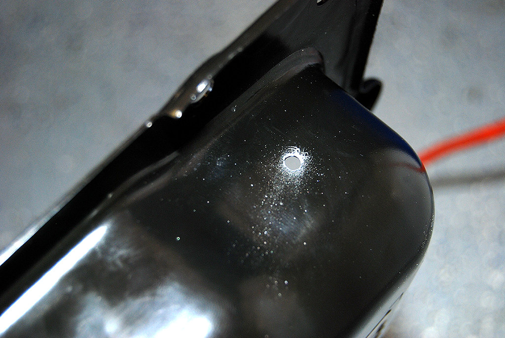
I drilled a pilot hole first.
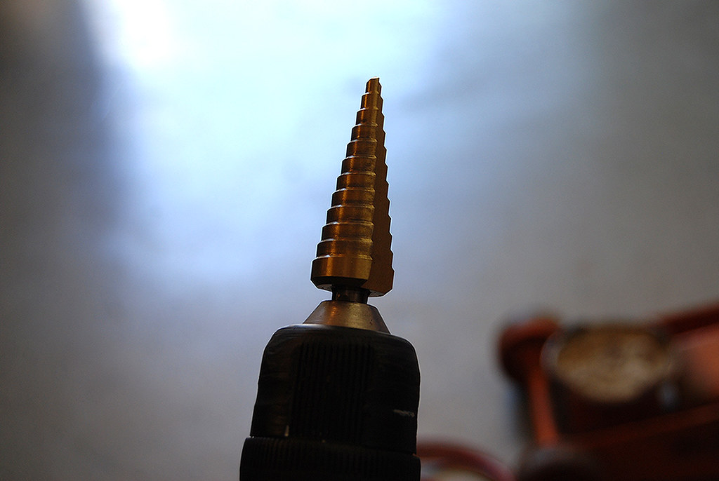
Then I used a step down bit to drill the holes.
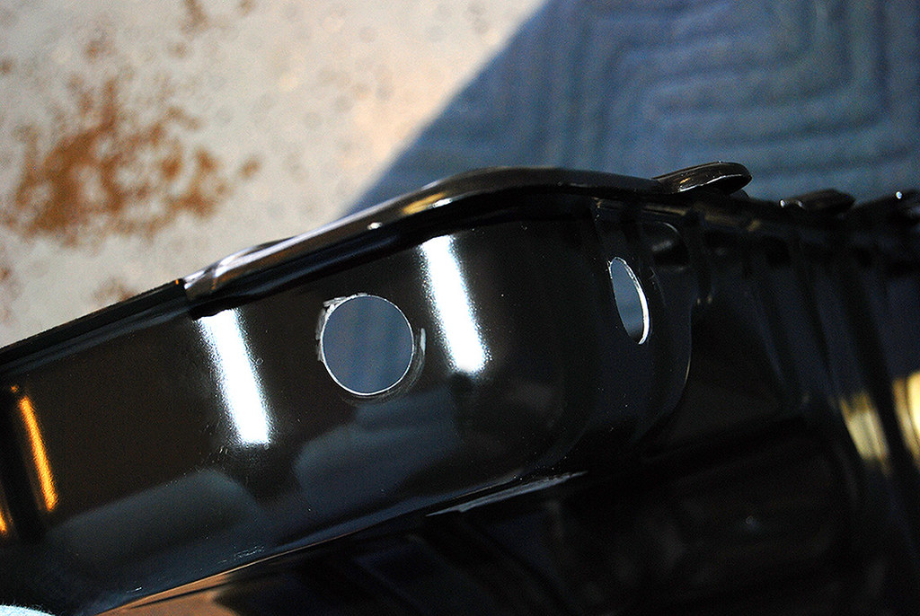
Then I put them in. They worked great! Here you can see how they look from the inside.
I then reinstalled the oil pan as per specifications as seen here. Ford Service Manuals - IN-VEHICLE REPAIR Pan.pdf
I moved the studded location over one and moved it on the wire harness as well.
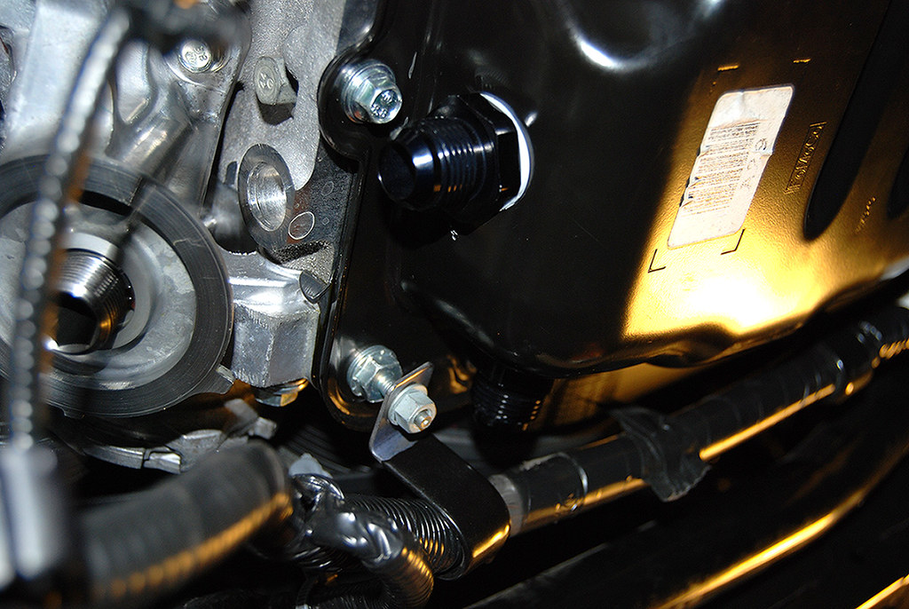
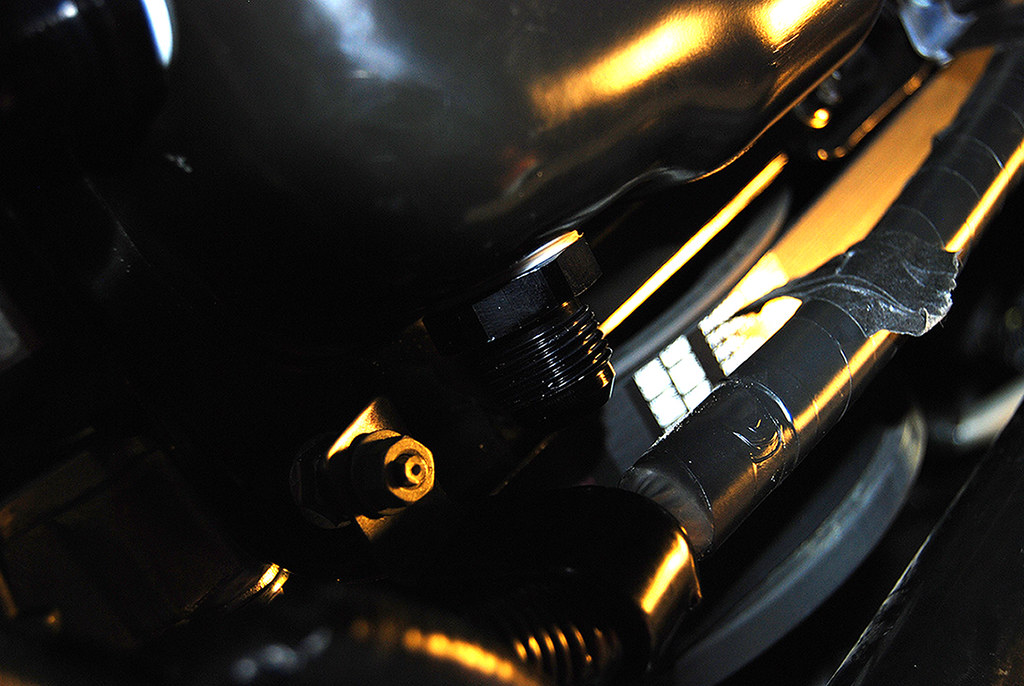
Here is the front fitting.
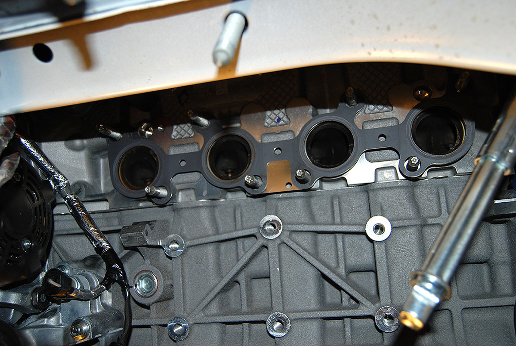
Next up was the drivers side header. I had to move the motor around a little to give me the clearance needed to slide it into place. I also had to take out and put back in all the studs. I was able to reuse all but one. I then torqued them down to specification as seen here.
Ford Service Manuals - IN-VEHICLE REPAIR Manifold - LH.pdf
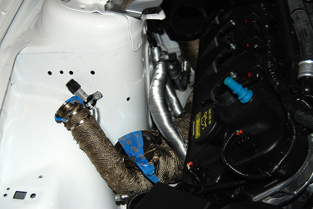
Back up top it looked like this.
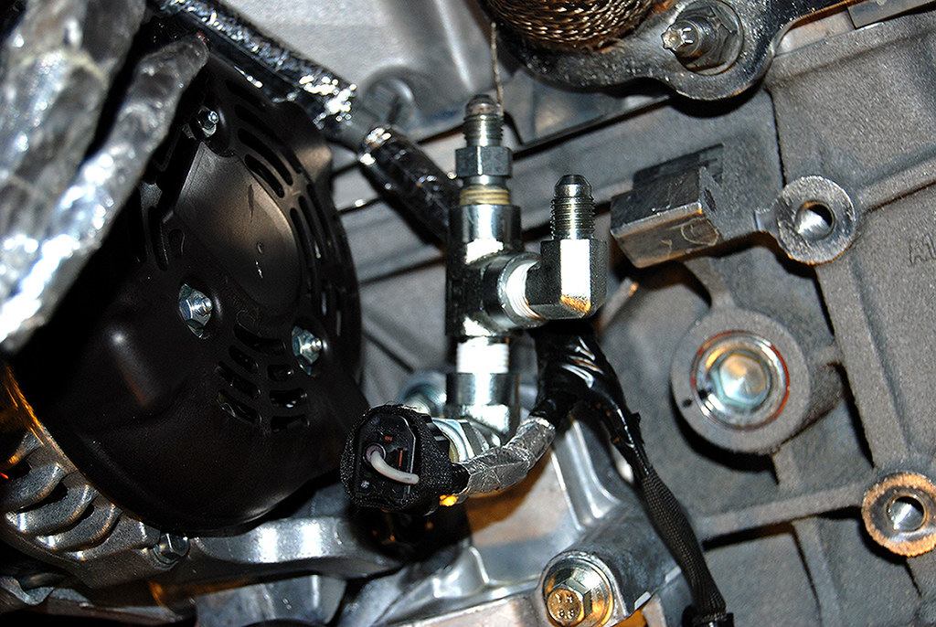
Next up was to install the oil feed fittings for the turbos.
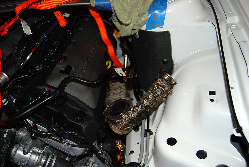
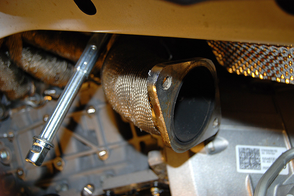
While I was at it I also installed the down pipe for the drivers side while I had the extra room. I just left it loose for now.
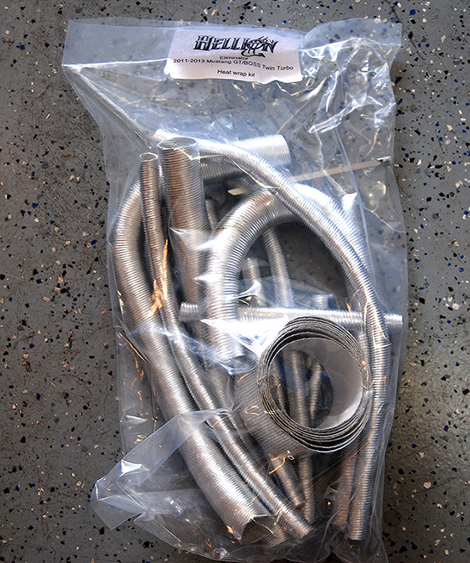
I was able to install the heat shielding.
Here is the package of different shields Hellion sends with the kit. Each are cut to specific lengths and go right along with the install instructions.
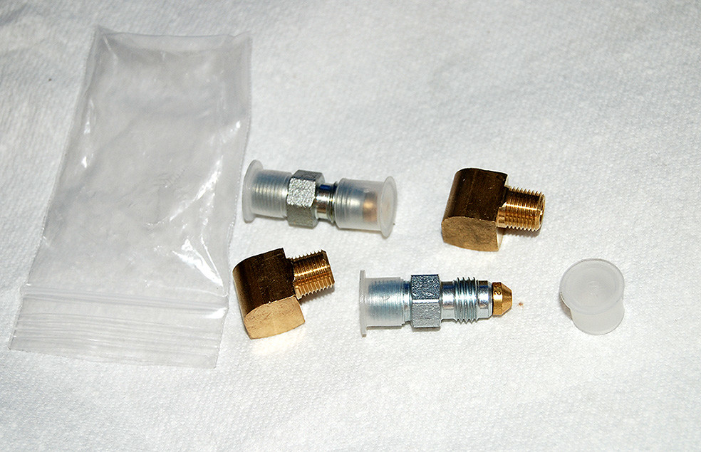
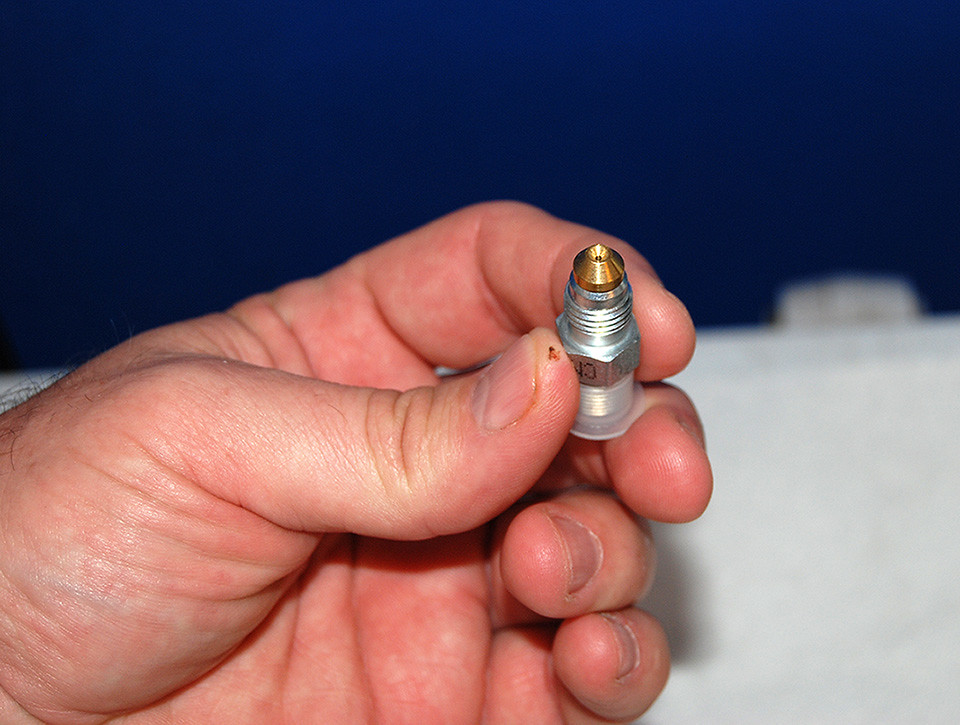
They sent me the restrictors for the oil feed lines. They use nitrous jets to reduce the amount of oil pressure to the turbos.
Here's what they sent. As you can see they machine fittings custom to accommodate the nitrous jets.
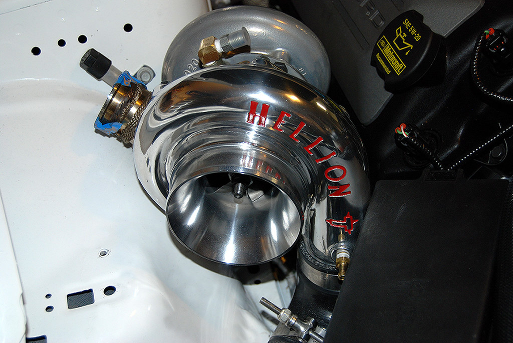
And the part most people like to see...........:coolman:
Got the passenger side turbo on.
Front clip off.
Front suspension removed.
Since I was removing the K-Member, I decided to use the factory strut tower along with some come along straps to help hold the motor. I put them near the ends where it had more support from the towers. Worked perfect!
The crank pulley has 3 bars that I used 2 of them to hook to.
With the engine supported, I unhooked the steering and dropped the K-Member.
That left room to pull the oil pan off so I can have fittings put in properly without punching holes in it and using the tap. I am not a fan of that technique.
By removing the K-Member and motor mounts, it made it much easier to get to the headers. For the passenger side I had to CAREFULLY coerce the A/C line a little to get to the front bolt. But it went easy enough with little drama.
Here's a good shot of the front factory Wideband O2's.
Here are the bulkhead fittings that I am using for the oil drain back.
I drilled a pilot hole first.
Then I used a step down bit to drill the holes.
Then I put them in. They worked great! Here you can see how they look from the inside.
I then reinstalled the oil pan as per specifications as seen here. Ford Service Manuals - IN-VEHICLE REPAIR Pan.pdf
I moved the studded location over one and moved it on the wire harness as well.
Here is the front fitting.
Next up was the drivers side header. I had to move the motor around a little to give me the clearance needed to slide it into place. I also had to take out and put back in all the studs. I was able to reuse all but one. I then torqued them down to specification as seen here.
Ford Service Manuals - IN-VEHICLE REPAIR Manifold - LH.pdf
Back up top it looked like this.
Next up was to install the oil feed fittings for the turbos.
While I was at it I also installed the down pipe for the drivers side while I had the extra room. I just left it loose for now.
I was able to install the heat shielding.
Here is the package of different shields Hellion sends with the kit. Each are cut to specific lengths and go right along with the install instructions.
They sent me the restrictors for the oil feed lines. They use nitrous jets to reduce the amount of oil pressure to the turbos.
Here's what they sent. As you can see they machine fittings custom to accommodate the nitrous jets.
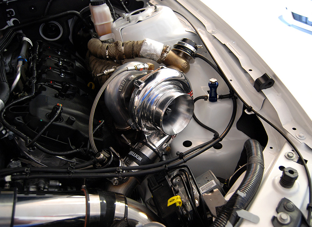
And the part most people like to see...........:coolman:
Got the passenger side turbo on.
 6/11/13, 02:39 PM
#2
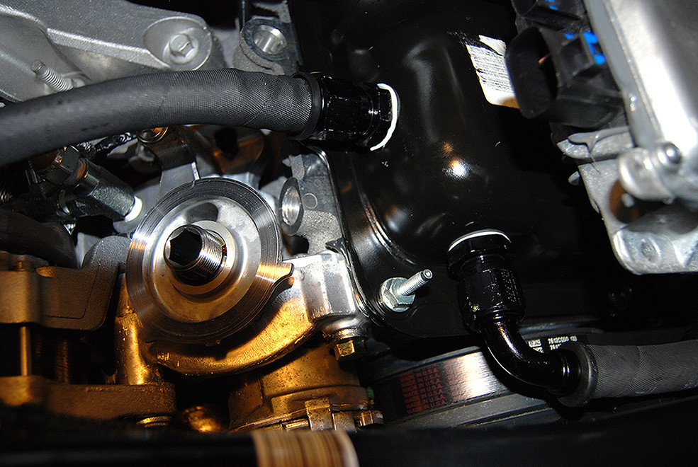
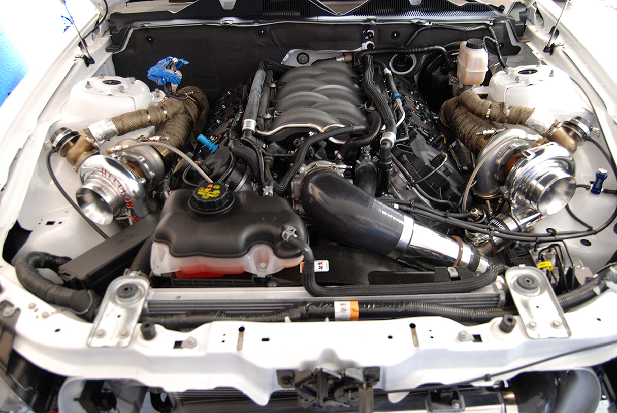
Got both turbo's mounted and both down pipes on. All oil lines and drain back connected and car filled back with oil and new filter.
Here are the drain back hoses.

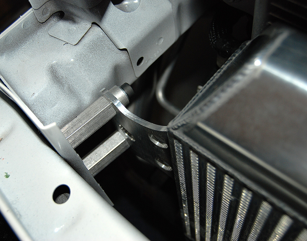
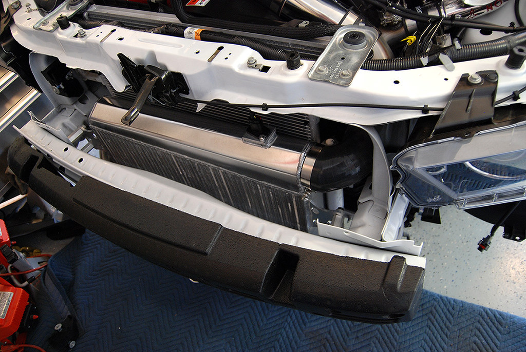
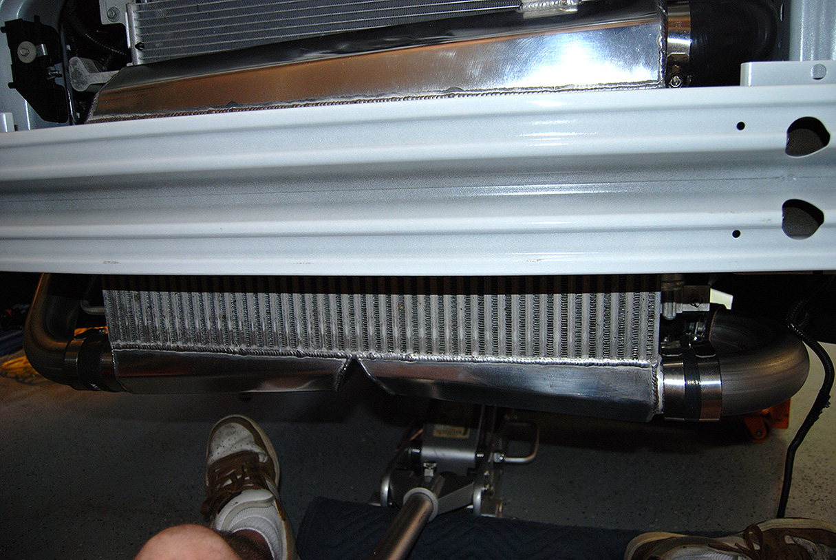
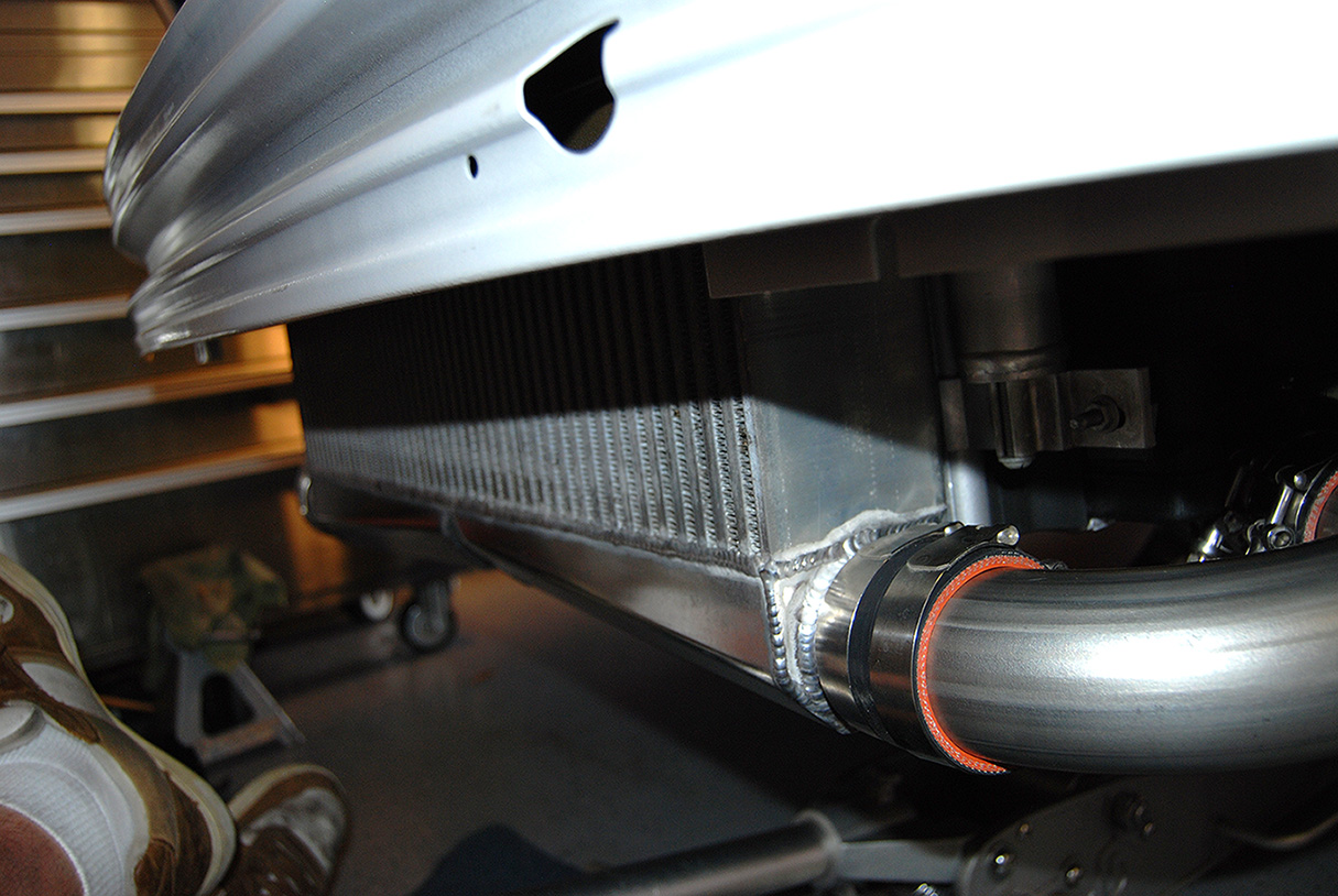
Got the intercooler mounted. It mounts to the factory bumper bolts via aluminum adapters. The mount is solid as a rock!
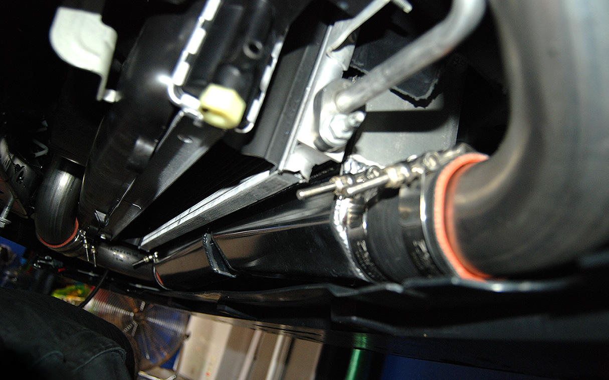
Connected the tube to the driver side turbo output pipe to the intercooler.
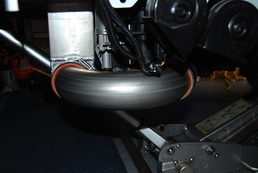
Also hooked up the passenger side as well.
Good shot of the how well the intercooler fits.
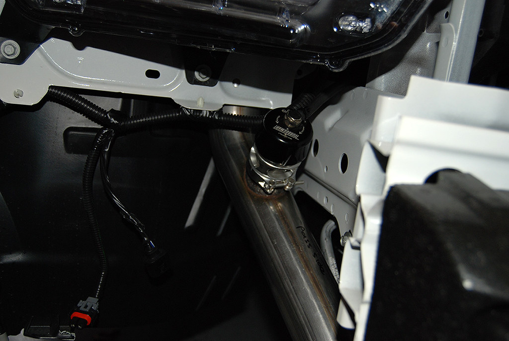
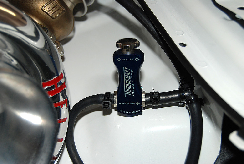
Also mounted the manual boost controller. This will be temporary and will be replaced by an E-Boost 2.
And here is how it sits now. Just waiting on the fuel system to show up!
Here are the drain back hoses.
Got the intercooler mounted. It mounts to the factory bumper bolts via aluminum adapters. The mount is solid as a rock!
Connected the tube to the driver side turbo output pipe to the intercooler.
Also hooked up the passenger side as well.
Good shot of the how well the intercooler fits.
Also mounted the manual boost controller. This will be temporary and will be replaced by an E-Boost 2.
And here is how it sits now. Just waiting on the fuel system to show up!
6/11/13, 02:39 PM
#3
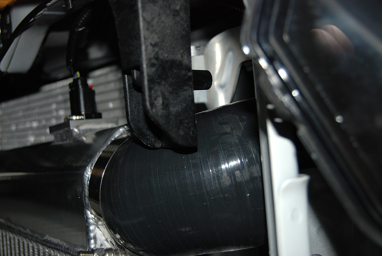
First, a couple of pictures of the intercooler. This thing is built like a tank!
I put the air deflector back in, but had to trim the bottom a little.
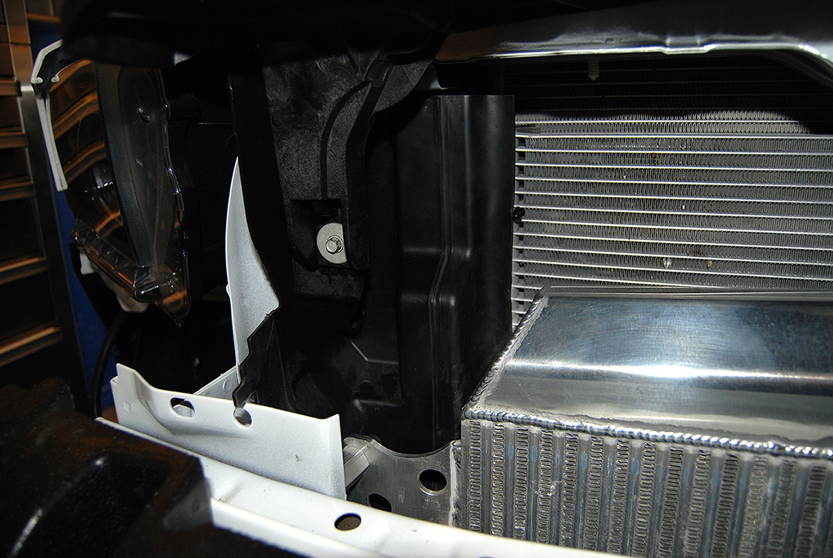
On the drivers side, I had to leave the air deflector off. Also, one of the brackets for the front grill support would not fit due to where the tube runs from the intercooler.
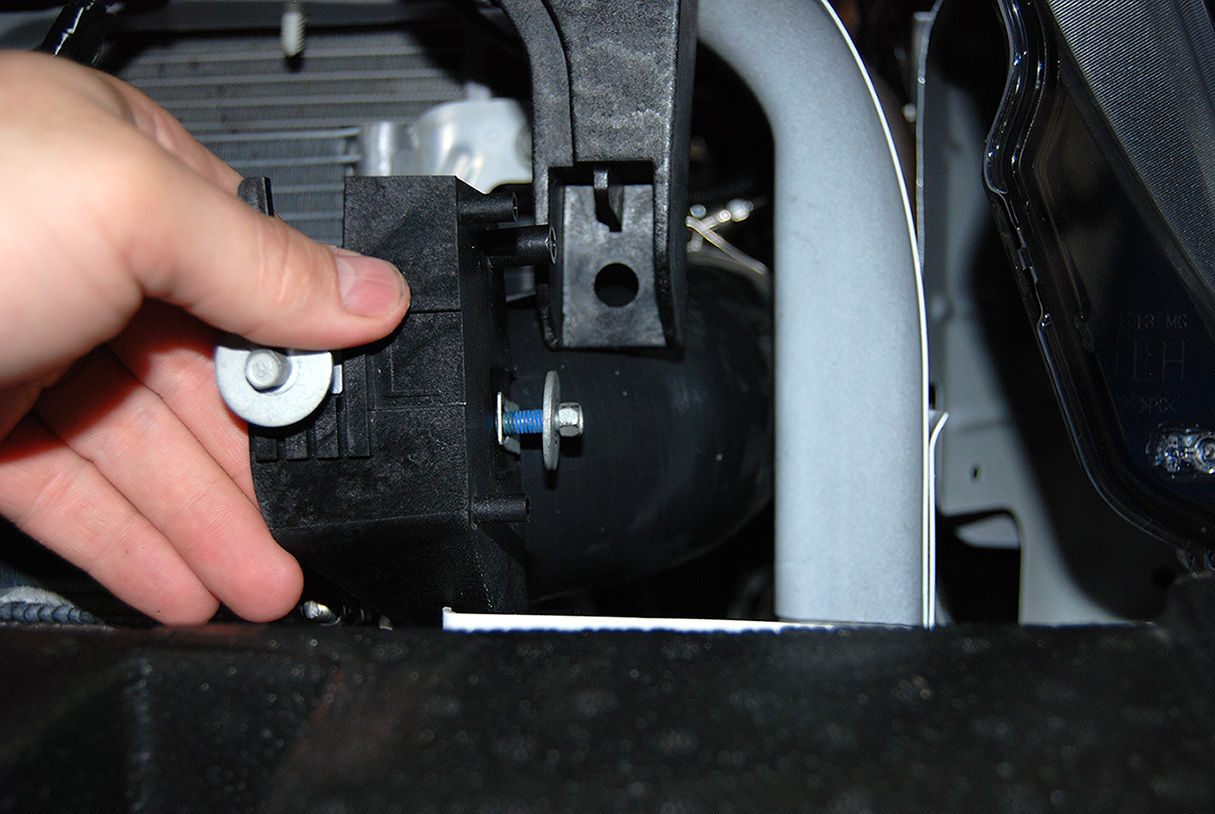
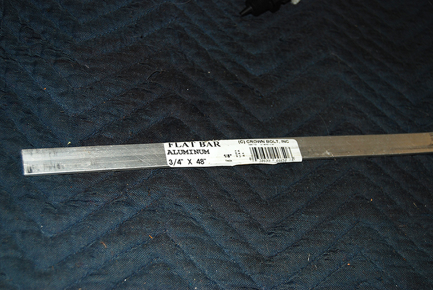
So I decided to fab up a small bracket real quick to take care of that. I used some aluminum flat stock I had laying around.
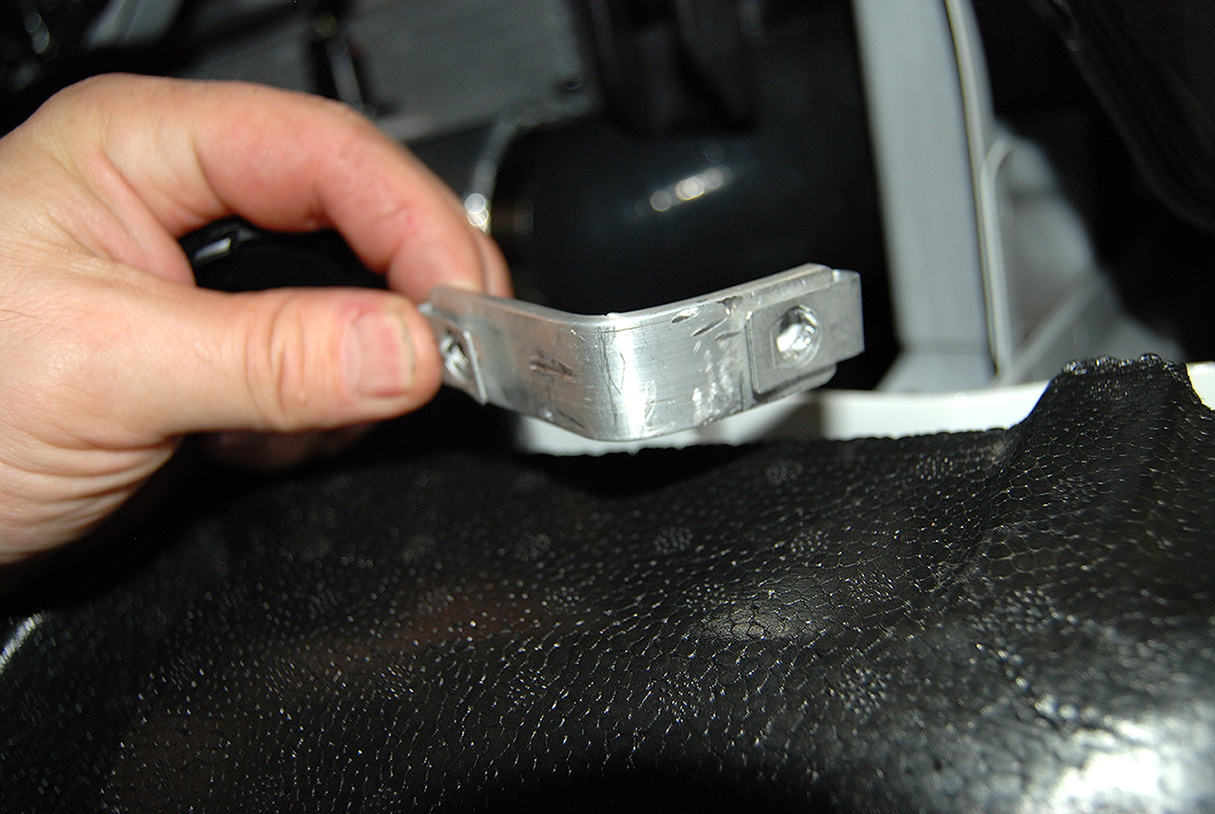
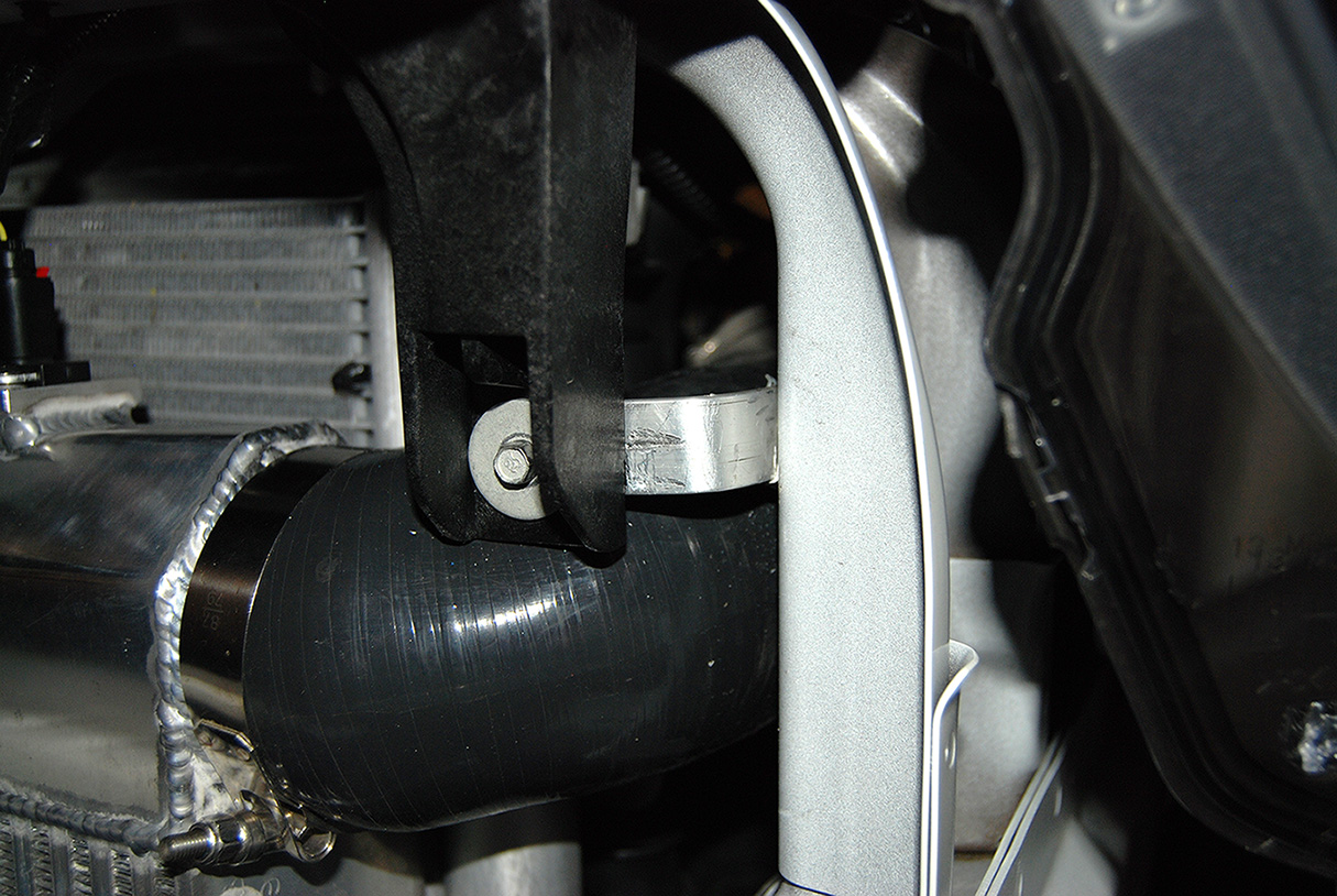
In just a few minutes I had this. I reused the stock bolts and fasteners.
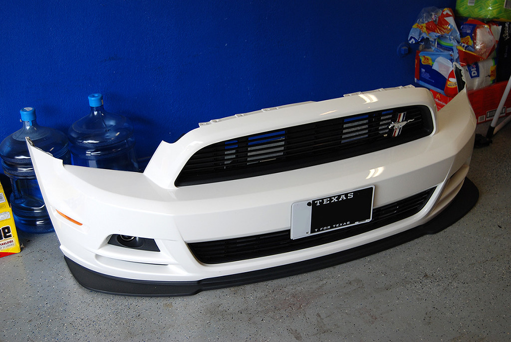
Then I put the front bumper cover back on. I know some people were asking about fog light clearance. No problem at all! It's not even close!
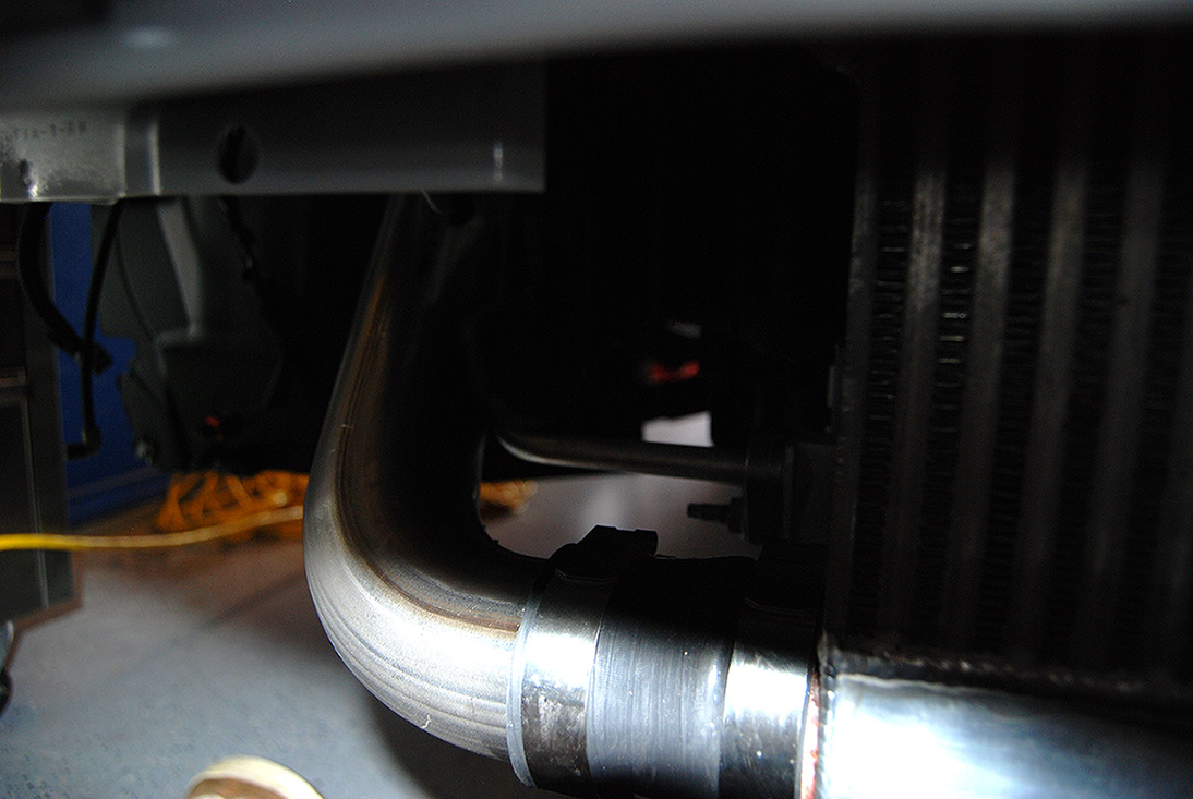
The pipes and intercooler tuck under the front bumper perfect!
That's all for now.
I put the air deflector back in, but had to trim the bottom a little.
On the drivers side, I had to leave the air deflector off. Also, one of the brackets for the front grill support would not fit due to where the tube runs from the intercooler.
So I decided to fab up a small bracket real quick to take care of that. I used some aluminum flat stock I had laying around.
In just a few minutes I had this. I reused the stock bolts and fasteners.
Then I put the front bumper cover back on. I know some people were asking about fog light clearance. No problem at all! It's not even close!
The pipes and intercooler tuck under the front bumper perfect!
That's all for now.
6/11/13, 02:40 PM
#4
I received my fuel system!
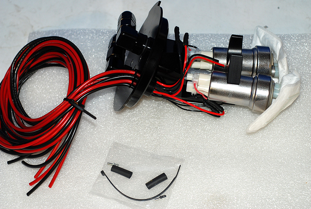
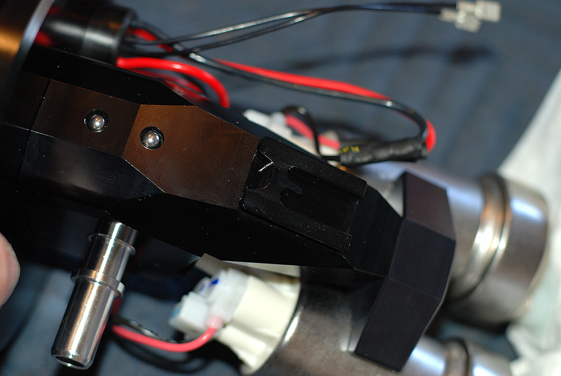
Fore Fuel Hat with (2) Walbro 465 pumps.
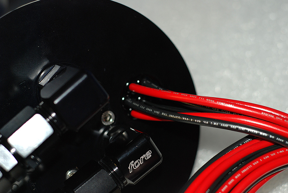
It hooks up to the factory cross over.
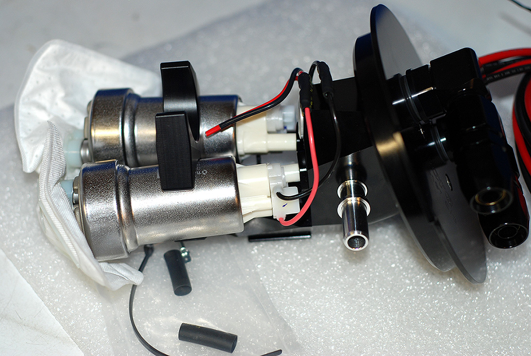
I opted for the triple hat. This will allow me to add a third pump if I choose to later on. Also, you can see the new hats have no fuel hose in the tank. The pumps slide into "Modules" designed for each pump and are sealed with Viton O-Rings. You can see where the third pump is plugged off.
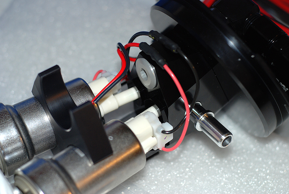
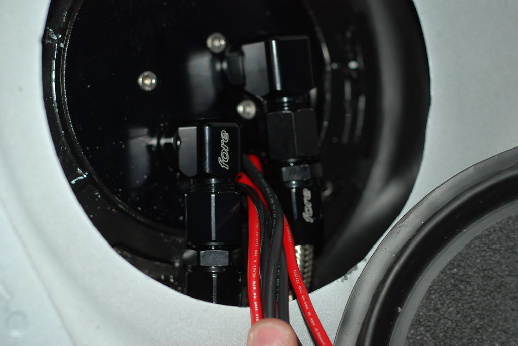
Here you can see where the wires are sealed as they go through the top hat.
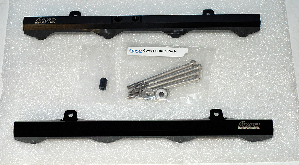
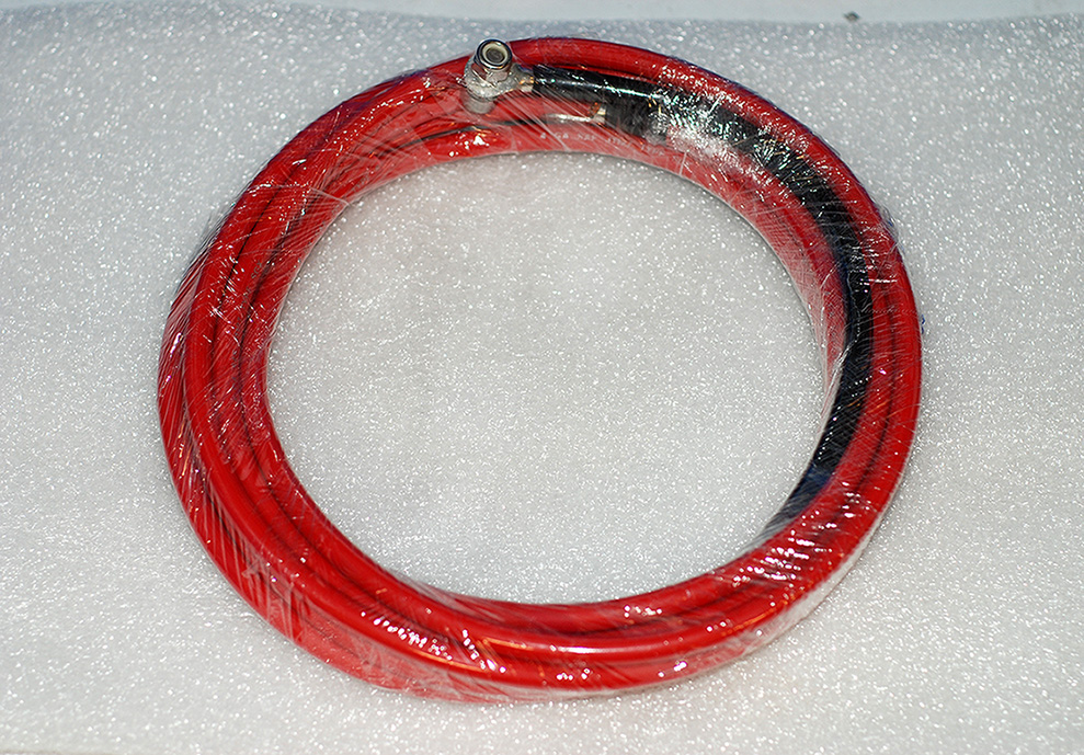
Here is the fuel rail kit. Simply stunning!
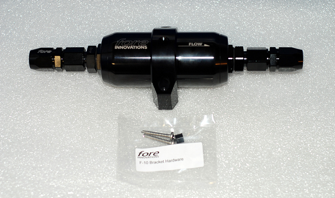
I opted for the fuel filter with 10 micron stainless element and billet mount. This also comes with install screws and plug. A nice touch.
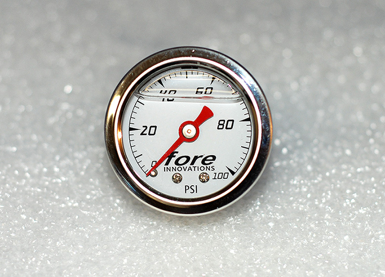
I also decided to get the fuel pressure gauge as well.
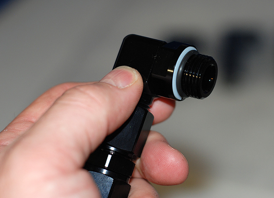
The system came with (4) 90* swivel fittings.
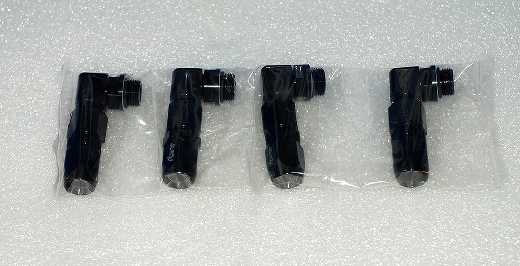
They seal with O-Rings.
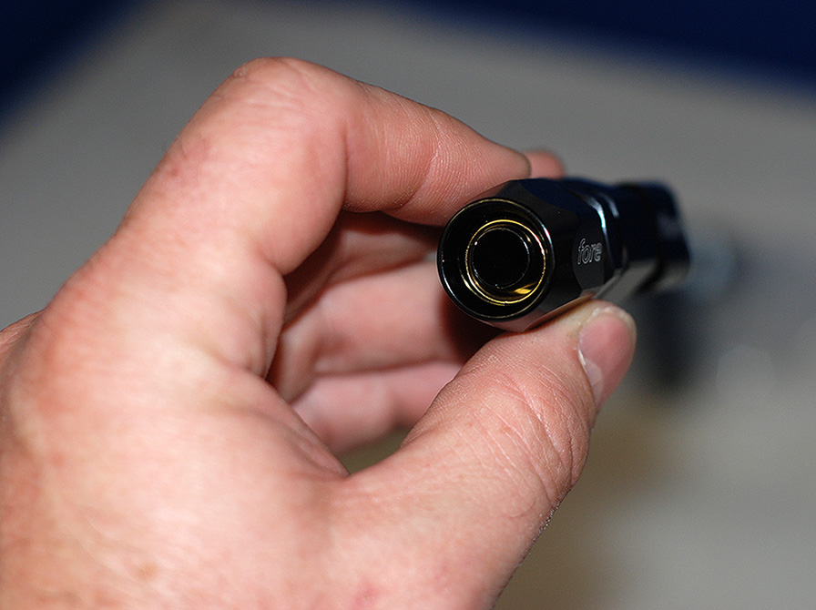
Here you can see where the hose connects.
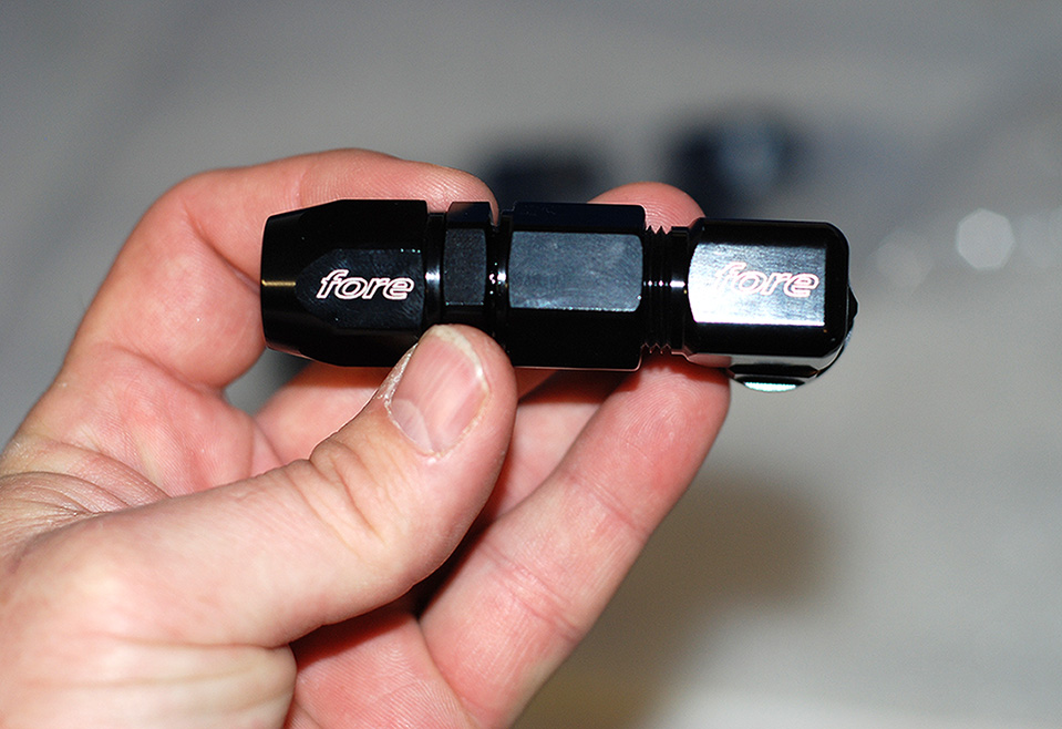
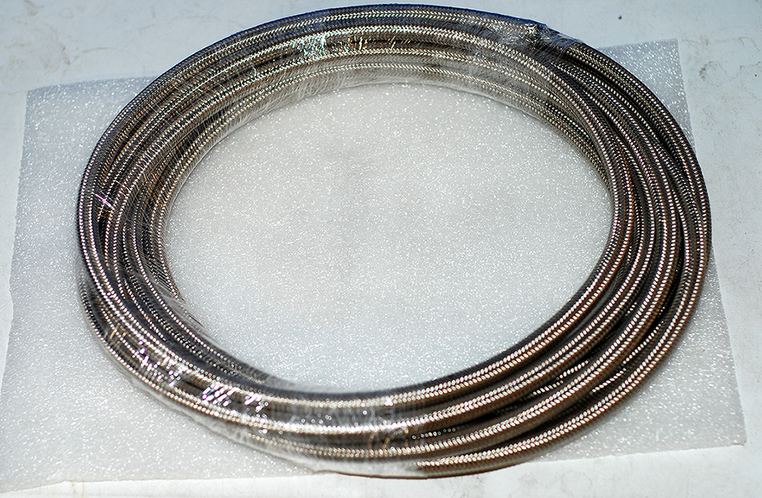
I am going with "New PTFE" -8 line with "Black" inner hose instead of the "White" clear. The white apparently can discharge small electrical "Arc's" over time which can cause small tiny pin holes over time. The new black is "Aircraft Approved".
For wiring I chose to go with the "FC3" controller. It allows very easy hook up and was specifically designed for this fuel system.
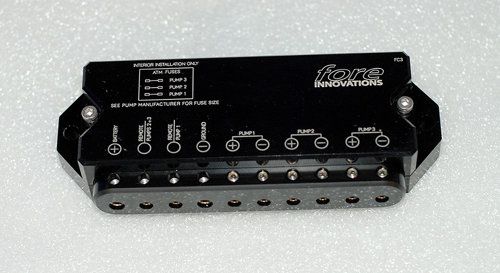
It comes with 4 Gauge wiring for power and ground.
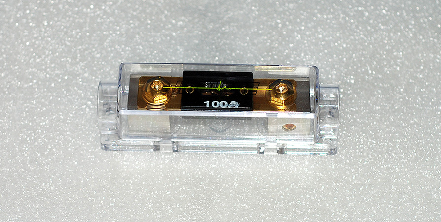
It also comes with 100 AMP inline fuse.
Now I just have to install all this!
Fore Fuel Hat with (2) Walbro 465 pumps.
It hooks up to the factory cross over.
I opted for the triple hat. This will allow me to add a third pump if I choose to later on. Also, you can see the new hats have no fuel hose in the tank. The pumps slide into "Modules" designed for each pump and are sealed with Viton O-Rings. You can see where the third pump is plugged off.
Here you can see where the wires are sealed as they go through the top hat.
Here is the fuel rail kit. Simply stunning!
I opted for the fuel filter with 10 micron stainless element and billet mount. This also comes with install screws and plug. A nice touch.
I also decided to get the fuel pressure gauge as well.
The system came with (4) 90* swivel fittings.
They seal with O-Rings.
Here you can see where the hose connects.
I am going with "New PTFE" -8 line with "Black" inner hose instead of the "White" clear. The white apparently can discharge small electrical "Arc's" over time which can cause small tiny pin holes over time. The new black is "Aircraft Approved".
For wiring I chose to go with the "FC3" controller. It allows very easy hook up and was specifically designed for this fuel system.
It comes with 4 Gauge wiring for power and ground.
It also comes with 100 AMP inline fuse.
Now I just have to install all this!
6/11/13, 02:40 PM
#5
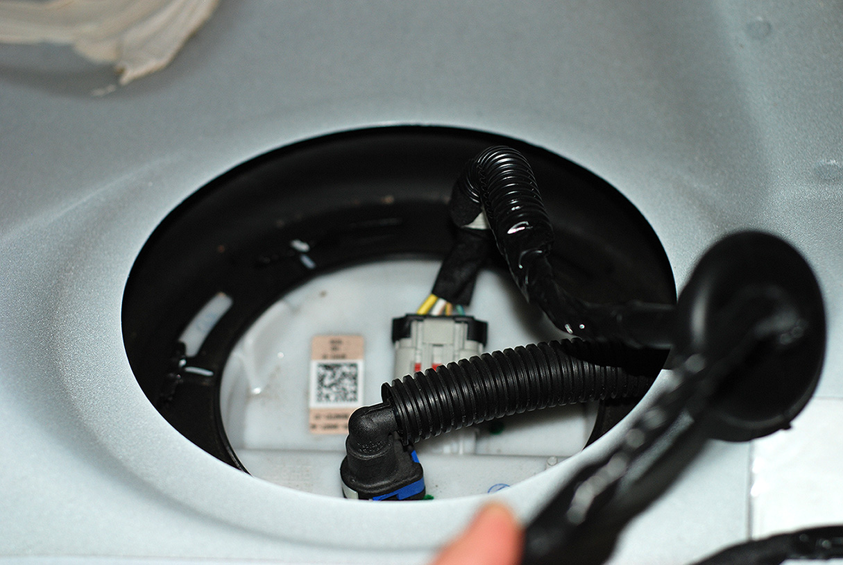
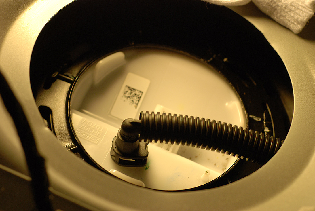
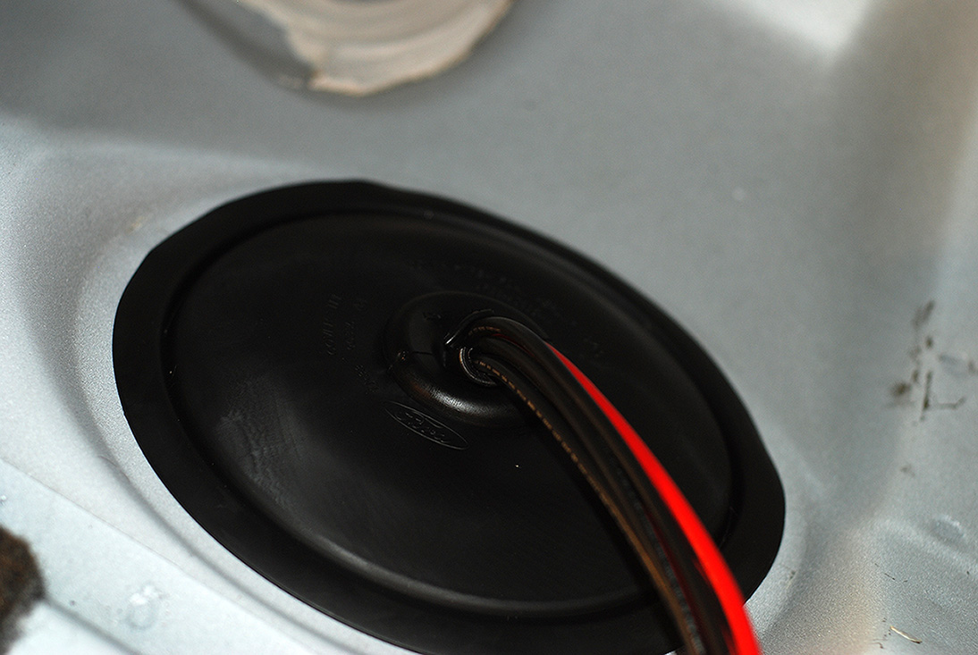
Took the back seat out and lowered the driver side tank just a little to give me some room to work. Under the seat you will find (2) large rubber grommets. The one on the drivers side is where the pump is located. The grommet just pulls off very easily. Then you will see this.
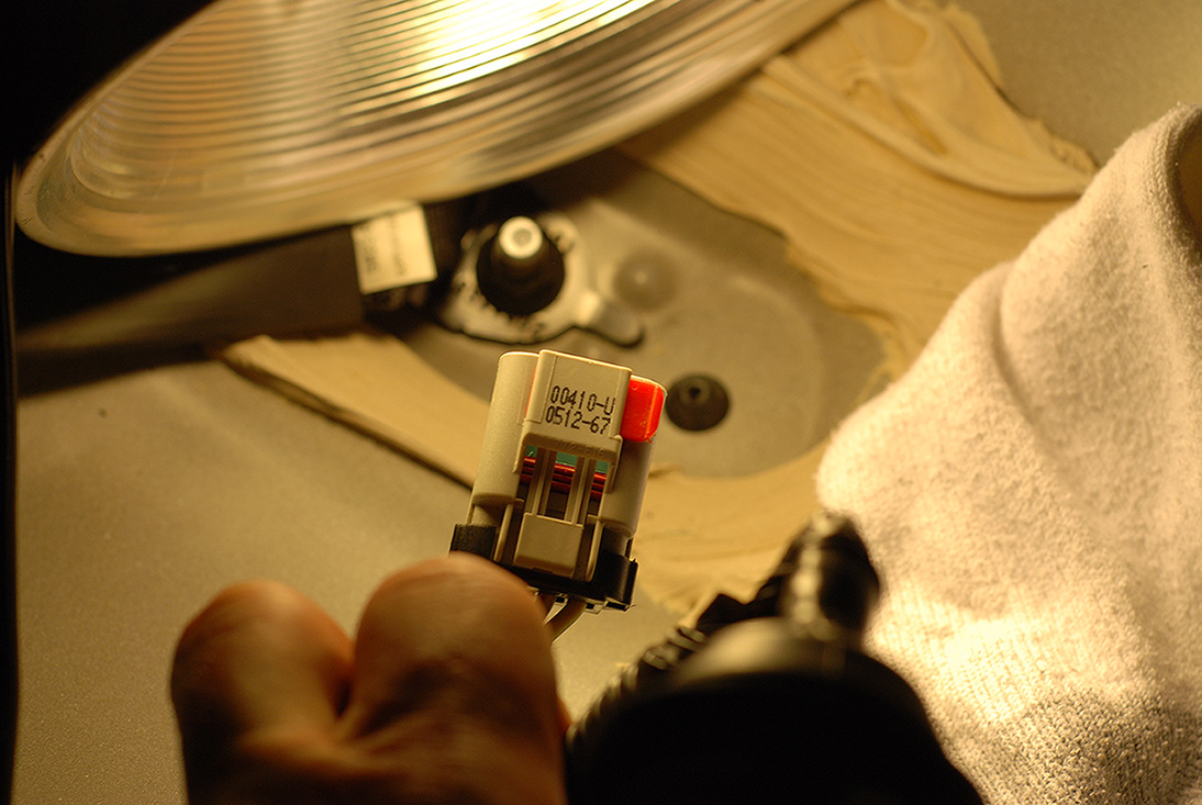
Seems a lot of the connectors Ford is using now have a safety latch. This one has the "Red" one you see here. You just slide it over and push the tab down to remove the connector.
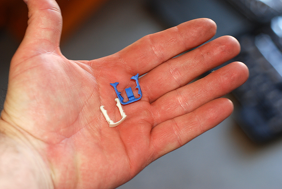
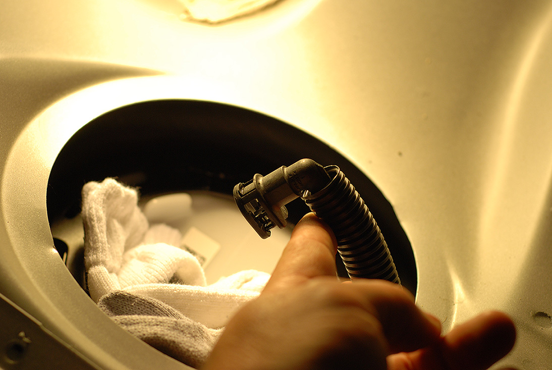
The fuel line is secured using these tabs. I used a small screwdriver to remove these. The "Blue" one comes off first followed by the "White" one. Again, the Blue one being the safety clip.
The ring around the stock hat comes off pretty much like all Mustangs. Counter Clockwise with a screwdriver and a rubber mallet.
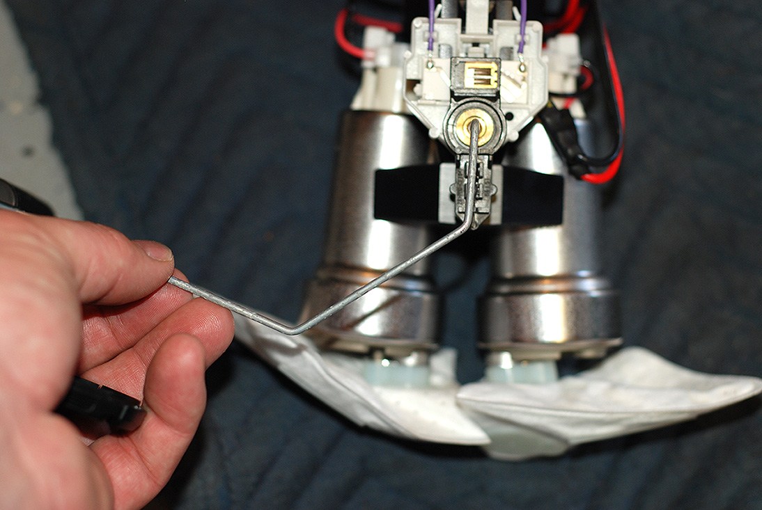
Once the ring is out of the way, you carefully lift the hat and disconnect the fuel lever arm. I used a pair of needle nose pliers to get it off. You have to "fish" it out as you are pulling the hat. It can damage very easily so you need to take extra caution when doing this!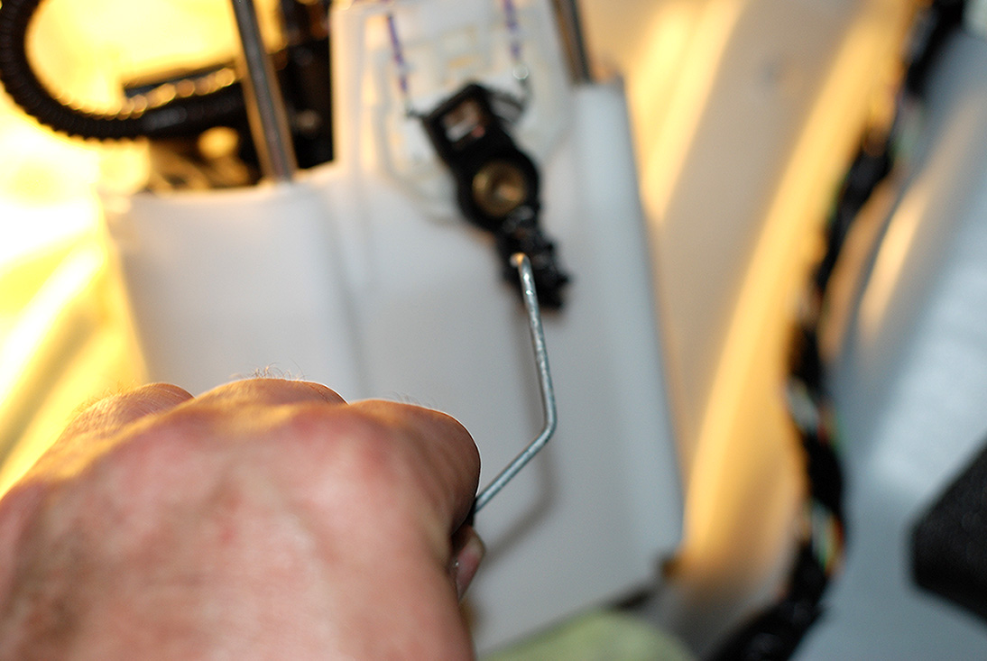
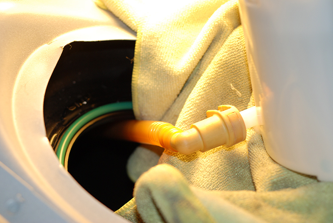
Then you slowly work the hat out of the tank. You will then have to unhook the fuel cross over tube. This is only held on by 1 clip.
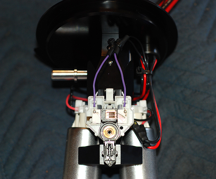
Once that is disconnected, you can get the hat out. Here is what the hat looks like for those that have not seen it.
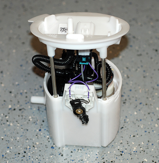
You have to remove the fuel sending unit and transfer it over to the new hat.
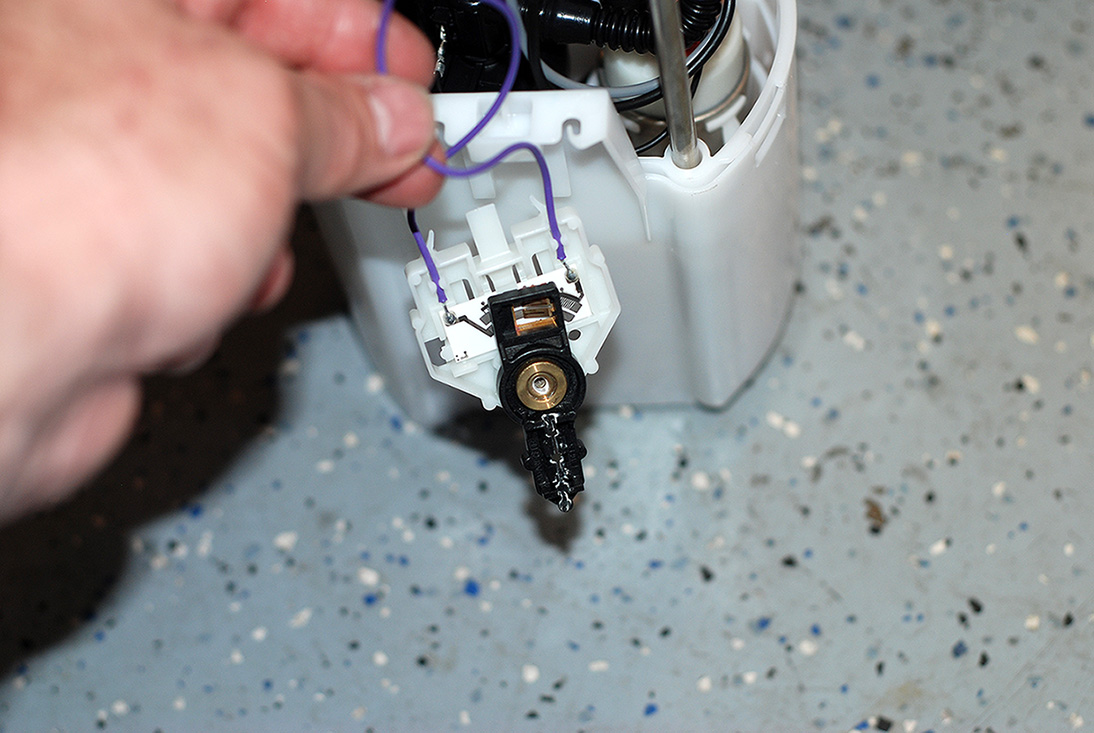
It has a small tab that holds it on and it slides right off.
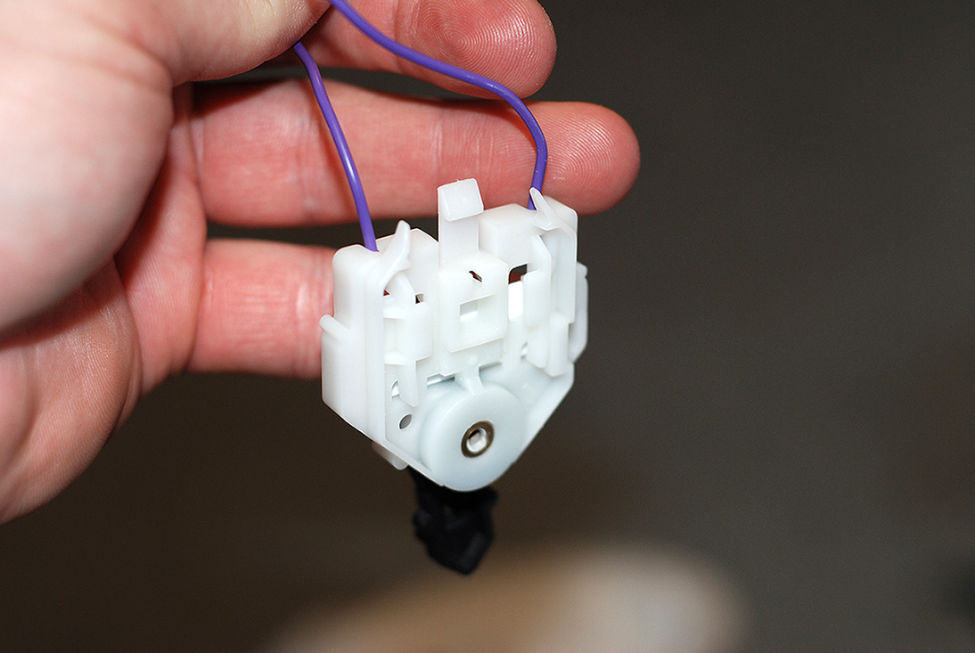
The new hat has is machined to accept the sending unit.
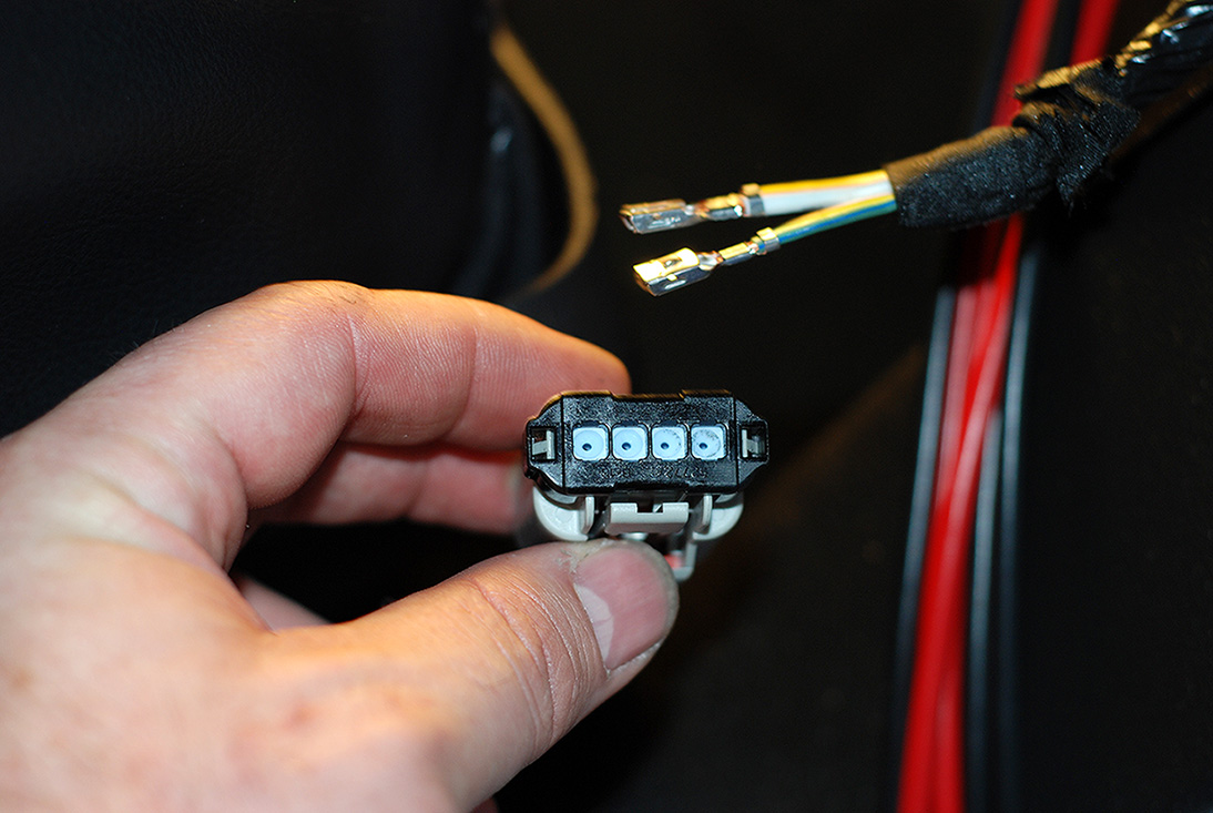
You will have to cut the plug off and install the supplied "Male" connectors to hook it to the wiring on the hat. Then you heat shrink the connectors and tie them with the supplied heast shrink and zip tie.
This shows how the float level goes when the hat goes back into the tank. You will lower them at the same time and snap the level back into place once in the tank.
Then you reinstall the hold down ring just like the stock hat was secured with. As you can see, I chose to "Bend" the opening a little on each side to help get the hold down ring in and out. I then tapped it back down before reinstalling the grommet.
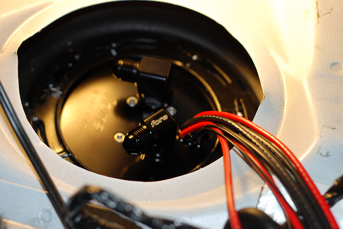
There is a grommet that the stock wires pass through the I chose to reuse.
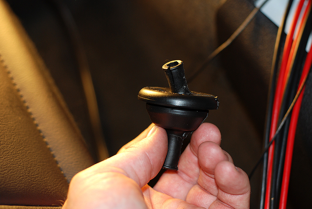
In order not to damage it, I just disassembled the factory plug. The "Teal" safety pops out with a small screwdriver and allows you to get to each wire. Small tabs hold each wire into the factory plug. You just slightly pry them away while pulling the wires out one by one.
I could have just cut the plug off, but I choose not to.
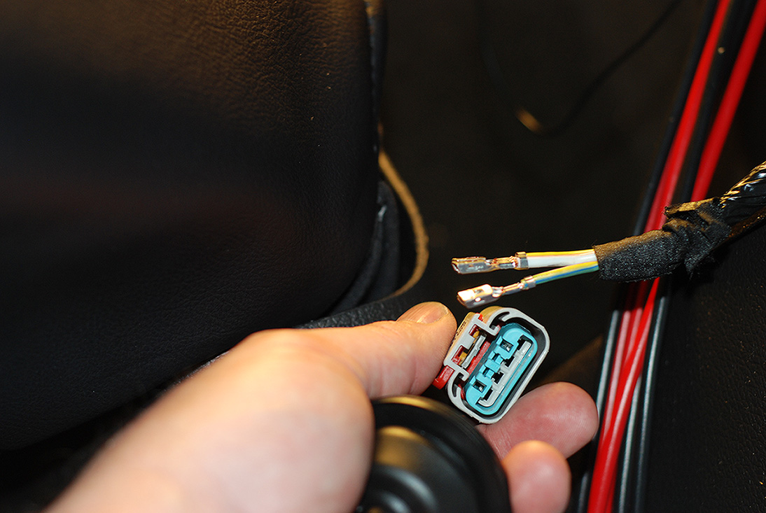
There is also a wire tab holder on the back side of the plug that can easily be removed with a small screwdriver as well.
With a little WD-40, the wires slide through no problem.
Well, that's all I finished for now. Next Up I will run the lines and mount the filter, regulator and rails.
Seems a lot of the connectors Ford is using now have a safety latch. This one has the "Red" one you see here. You just slide it over and push the tab down to remove the connector.
The fuel line is secured using these tabs. I used a small screwdriver to remove these. The "Blue" one comes off first followed by the "White" one. Again, the Blue one being the safety clip.
The ring around the stock hat comes off pretty much like all Mustangs. Counter Clockwise with a screwdriver and a rubber mallet.
Once the ring is out of the way, you carefully lift the hat and disconnect the fuel lever arm. I used a pair of needle nose pliers to get it off. You have to "fish" it out as you are pulling the hat. It can damage very easily so you need to take extra caution when doing this!
Then you slowly work the hat out of the tank. You will then have to unhook the fuel cross over tube. This is only held on by 1 clip.
Once that is disconnected, you can get the hat out. Here is what the hat looks like for those that have not seen it.
You have to remove the fuel sending unit and transfer it over to the new hat.
It has a small tab that holds it on and it slides right off.
The new hat has is machined to accept the sending unit.
You will have to cut the plug off and install the supplied "Male" connectors to hook it to the wiring on the hat. Then you heat shrink the connectors and tie them with the supplied heast shrink and zip tie.
This shows how the float level goes when the hat goes back into the tank. You will lower them at the same time and snap the level back into place once in the tank.
Then you reinstall the hold down ring just like the stock hat was secured with. As you can see, I chose to "Bend" the opening a little on each side to help get the hold down ring in and out. I then tapped it back down before reinstalling the grommet.
There is a grommet that the stock wires pass through the I chose to reuse.
In order not to damage it, I just disassembled the factory plug. The "Teal" safety pops out with a small screwdriver and allows you to get to each wire. Small tabs hold each wire into the factory plug. You just slightly pry them away while pulling the wires out one by one.
I could have just cut the plug off, but I choose not to.
There is also a wire tab holder on the back side of the plug that can easily be removed with a small screwdriver as well.
With a little WD-40, the wires slide through no problem.
Well, that's all I finished for now. Next Up I will run the lines and mount the filter, regulator and rails.
 6/11/13, 08:20 PM
#7
GT Member

Join Date: March 29, 2013
Posts: 161
Likes: 0
Received 0 Likes
on
0 Posts
Dude this is INSANE!! I really enjoyed your thread especially with all the effort you put into the install and uploading pics along the way. This is so cool because i have the same car in a manual. I love our car and it's color scheme. I wish i had half the skills you do so i could eventually do some work to my car (i'm only semi-mechanically inclined) no where near your level. Project looks amazing, hope you enjoy your new setup. Please update with videos when your done! Going to sound amazing.
6/11/13, 09:00 PM
#9
Member
Join Date: September 28, 2012
Posts: 44
Likes: 0
Received 0 Likes
on
0 Posts
Kevin I wondered when you were going to post that over here, its coming together great and looks flawless!
Funny thing another guy showed up at the friday meet with our same car in a 14...lol
Funny thing another guy showed up at the friday meet with our same car in a 14...lol
6/12/13, 06:34 PM
#10
Mach 1 Member
Wow, amazing, and the detail you are outlining in your pictures is great, including the clarity in the shots. As the other poster said you have some serious mechanical skills. There's no way I would even think about doing.
What are you plans for your car? Show car, track it, bad arsed cruiser? Keep up the good work!
What are you plans for your car? Show car, track it, bad arsed cruiser? Keep up the good work!
6/26/13, 10:57 AM
#12
Bullitt Member
Join Date: January 25, 2013
Location: Jersey
Posts: 460
Likes: 0
Received 0 Likes
on
0 Posts
Same,
OP how much boost do you plan on running? That TT kit makes some serious power I'm anxious to see what power youre going to be putting down. Whose tuning it for you any details as far as that goes? Im up in the air whether i want to go the turbo route or slap on a roush supercharger, decisions decisions.
OP how much boost do you plan on running? That TT kit makes some serious power I'm anxious to see what power youre going to be putting down. Whose tuning it for you any details as far as that goes? Im up in the air whether i want to go the turbo route or slap on a roush supercharger, decisions decisions.
6/30/13, 07:21 AM
#13
Dude this is INSANE!! I really enjoyed your thread especially with all the effort you put into the install and uploading pics along the way. This is so cool because i have the same car in a manual. I love our car and it's color scheme. I wish i had half the skills you do so i could eventually do some work to my car (i'm only semi-mechanically inclined) no where near your level. Project looks amazing, hope you enjoy your new setup. Please update with videos when your done! Going to sound amazing.
Thank you.
Wow, amazing, and the detail you are outlining in your pictures is great, including the clarity in the shots. As the other poster said you have some serious mechanical skills. There's no way I would even think about doing.
What are you plans for your car? Show car, track it, bad arsed cruiser? Keep up the good work!
What are you plans for your car? Show car, track it, bad arsed cruiser? Keep up the good work!
Same,
OP how much boost do you plan on running? That TT kit makes some serious power I'm anxious to see what power youre going to be putting down. Whose tuning it for you any details as far as that goes? Im up in the air whether i want to go the turbo route or slap on a roush supercharger, decisions decisions.
OP how much boost do you plan on running? That TT kit makes some serious power I'm anxious to see what power youre going to be putting down. Whose tuning it for you any details as far as that goes? Im up in the air whether i want to go the turbo route or slap on a roush supercharger, decisions decisions.
I will be tuning it myself.
This is more involved than a TVS, but I wanted something a little different.
6/30/13, 07:22 AM
#14
OK. I got a little wiring done.
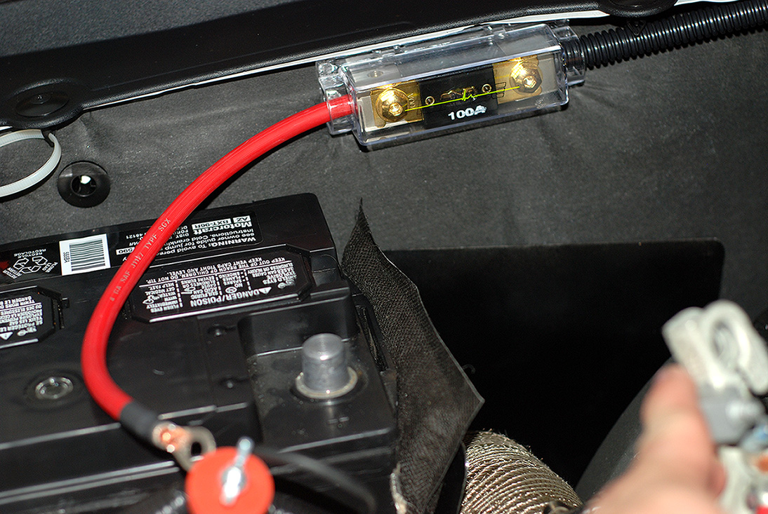
Mounted the 100 AMP inline fuse holder near the battery for safety and ease of accessibility.
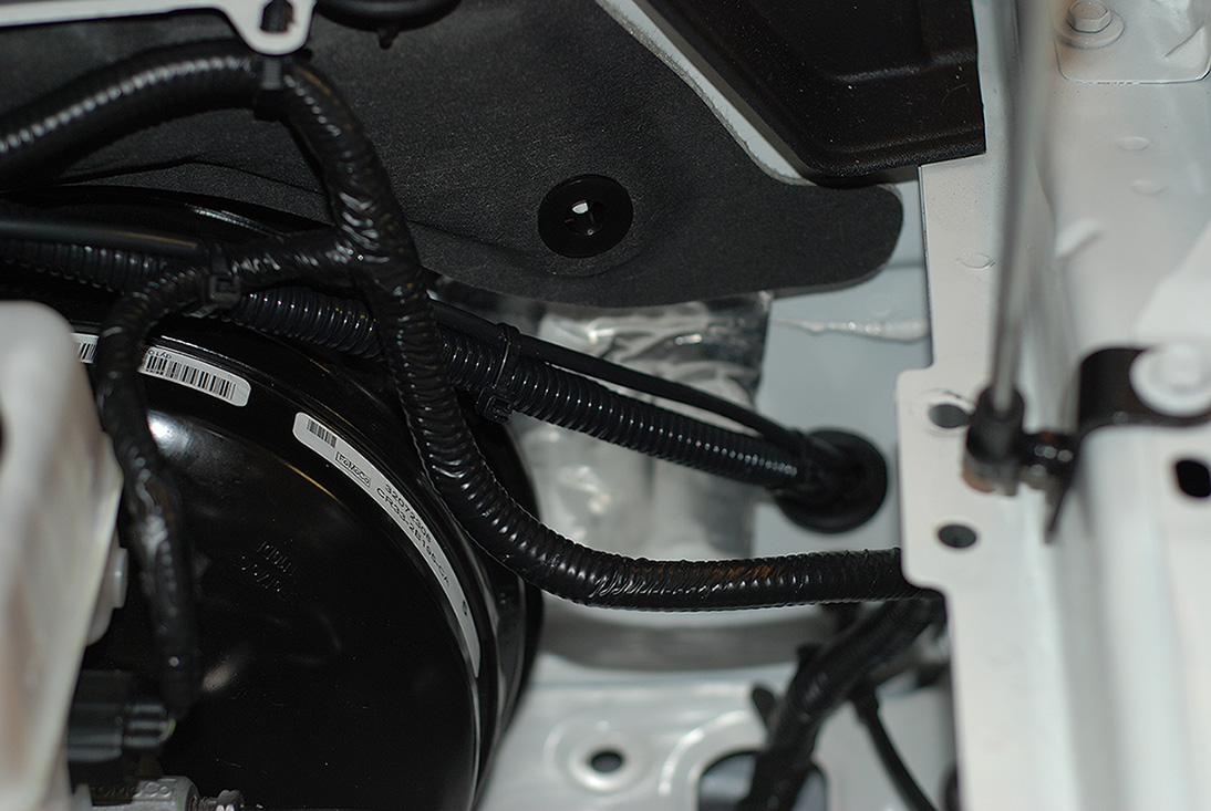
I found a good use for the old "Sound Tube" hole in the firewall. I got a grommet from the auto parts store and ran the power wire and the Hobbs Switch wire through it to the back.
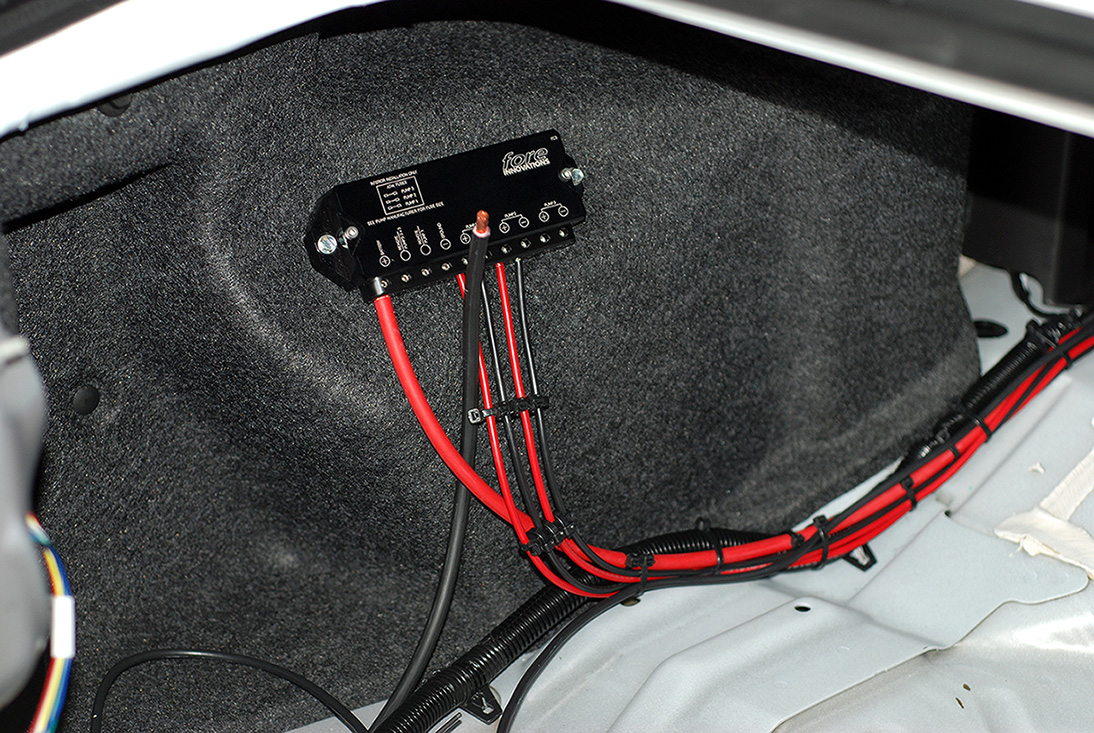
Once into the trunk, I found a suitable and accessible location to mount the FC3 Controller. I routed all the wires along with the factory routings.
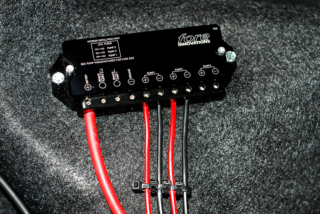
Here you can see how the controller is wired. I still have to run the triggers and hook up the ground last. Since I am only running 2 pumps, I left "pump 3" unhooked.
Mounted the 100 AMP inline fuse holder near the battery for safety and ease of accessibility.
I found a good use for the old "Sound Tube" hole in the firewall. I got a grommet from the auto parts store and ran the power wire and the Hobbs Switch wire through it to the back.
Once into the trunk, I found a suitable and accessible location to mount the FC3 Controller. I routed all the wires along with the factory routings.
Here you can see how the controller is wired. I still have to run the triggers and hook up the ground last. Since I am only running 2 pumps, I left "pump 3" unhooked.
6/30/13, 07:22 AM
#15
OK. Had a chance to run the feed and return lines today and mount the filter.
Over all, the new PTFE fittings were relatively easy to assemble.
Here is the new PTFE line with the black "Conductive Carbon" inner core. This is approved for air craft and will not degrade over time or cause static like other PTFE line.
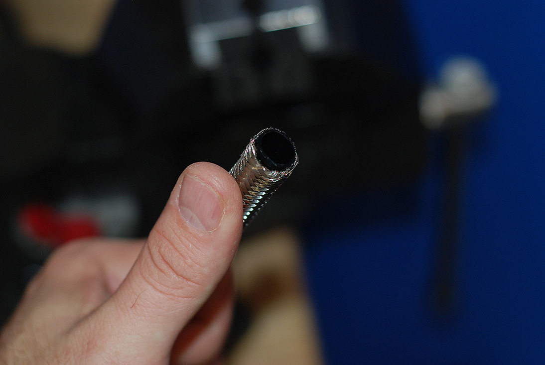
First step is to pull back the stainless steel so you have room for the Olive connector.
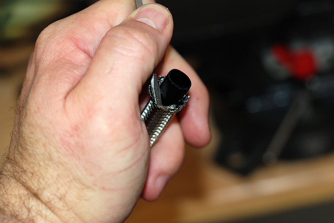
Next I installed the Olive between the stainless and PTFE inner hose.
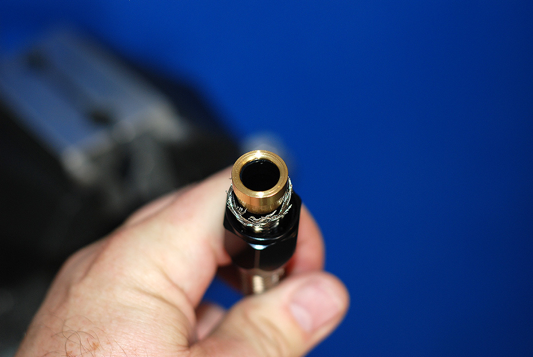
Then I put the end fitting into my soft jaws in my vise with very little pressure and pushed on the hose to the fitting.

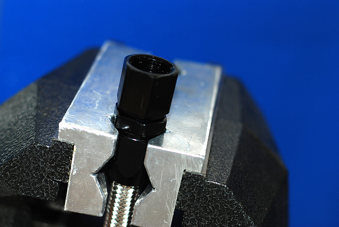
Then I turned the hose so it was facing up in the vise and tightened the fitting down with a 7/8" socket and ratchet.
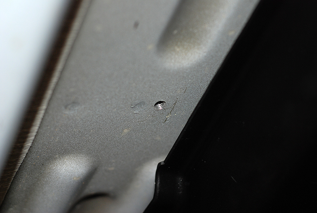
Next up was to mount the filter. The filter comes with self tapping screws, but the floor pan where I wanted to mount it was very thick. So I drilled and tapped it.
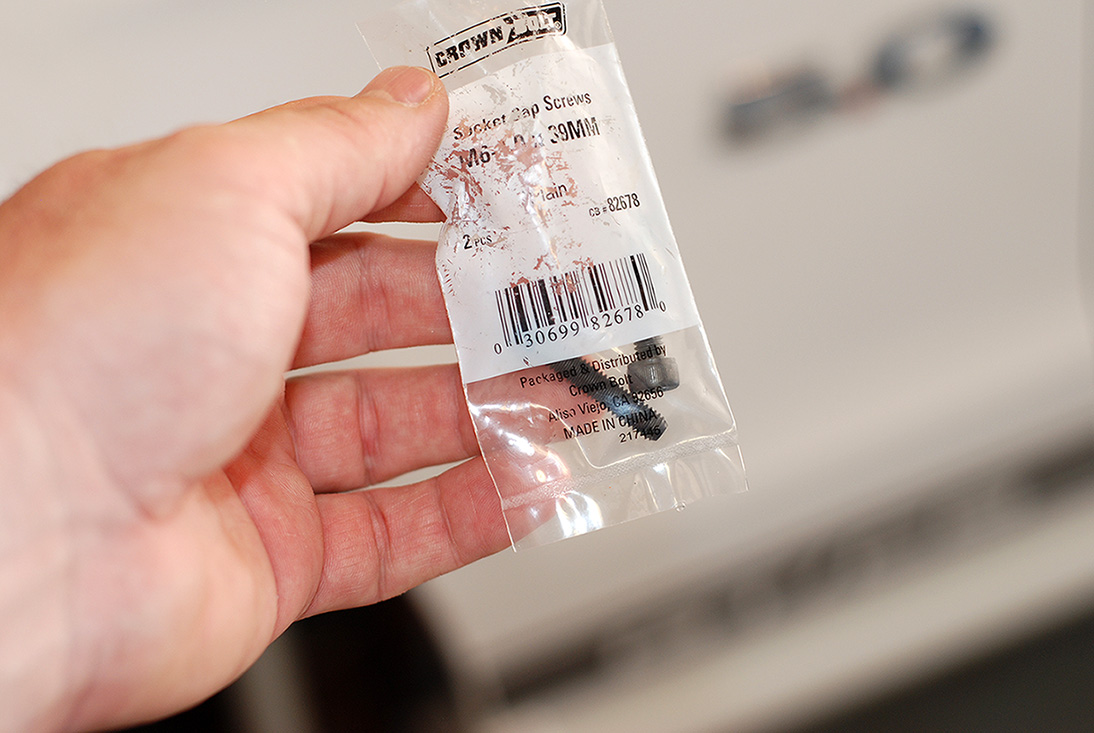
Here are the screws I used to secure it to the bottom of the car.
I decided to mount the filter right behind the rocker panel on the drivers side for easy serviceability.
Here are the hoses hooked up to the hat.
I just followed the factory routings for ease of installation. Here's where it runs down from the front corner of the tank.
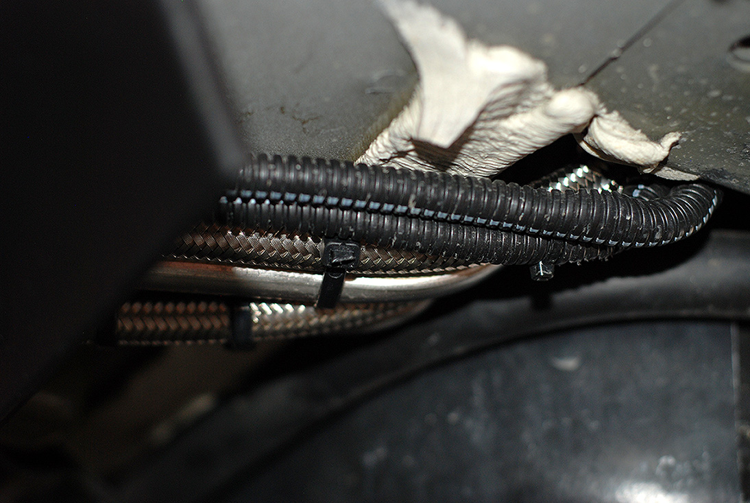
There are two plastic factory guards under the car that help protect the lines and I chose to run the hose under like the factory. You can see where I ran the feed line out for the filter.
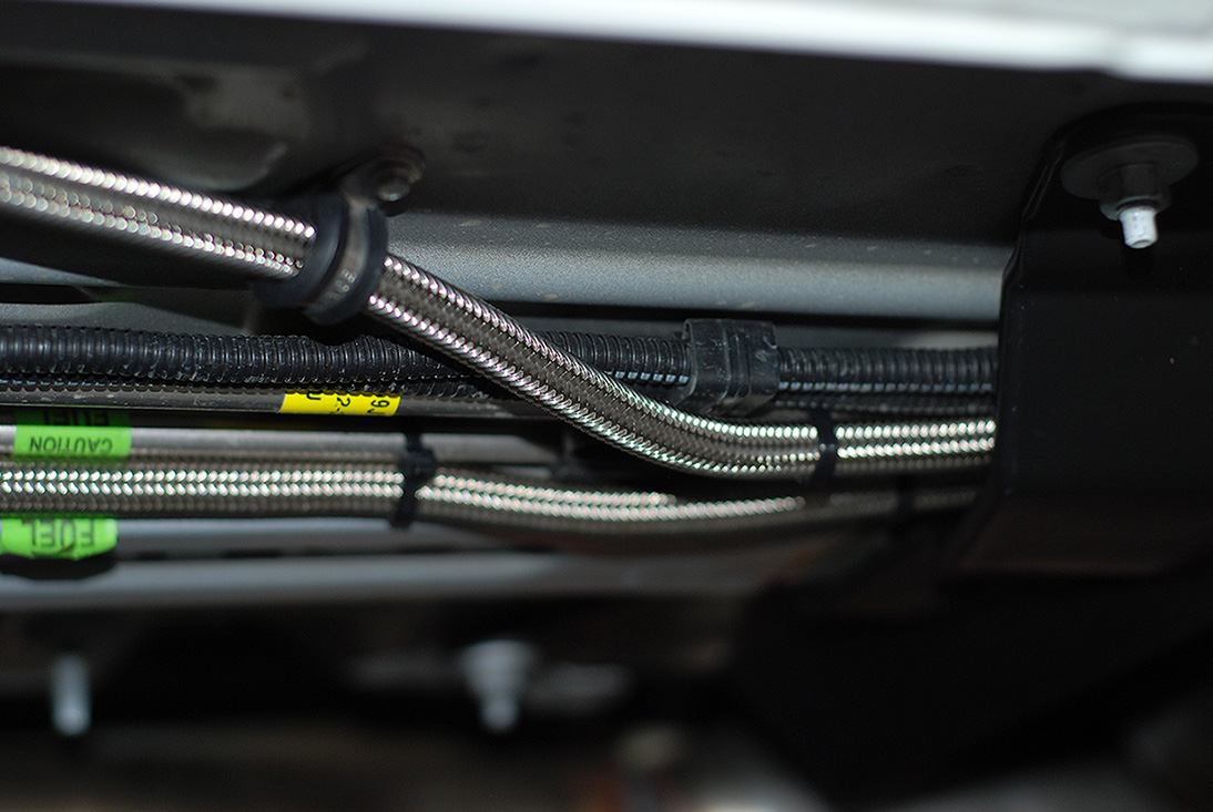
Here I used another supplied cushion clamp and ran the line back under the factory panel.
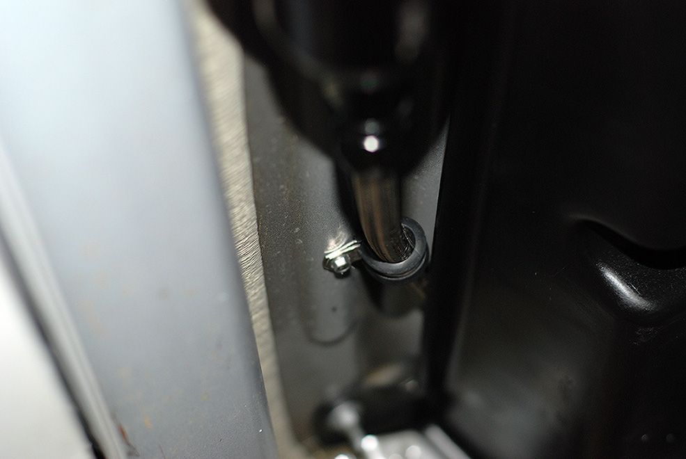
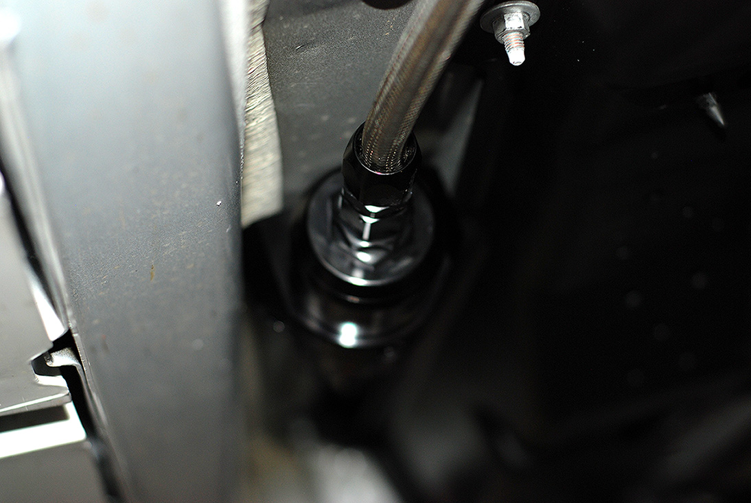
Here is where the lines runs up the inner wheel well following the factory lines.
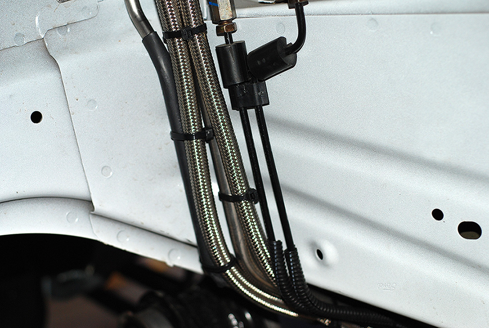
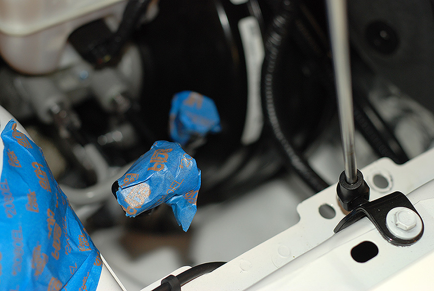
Then up into the engine bay behind the drivers side strut tower. I taped off the ends so nothing would get into them.
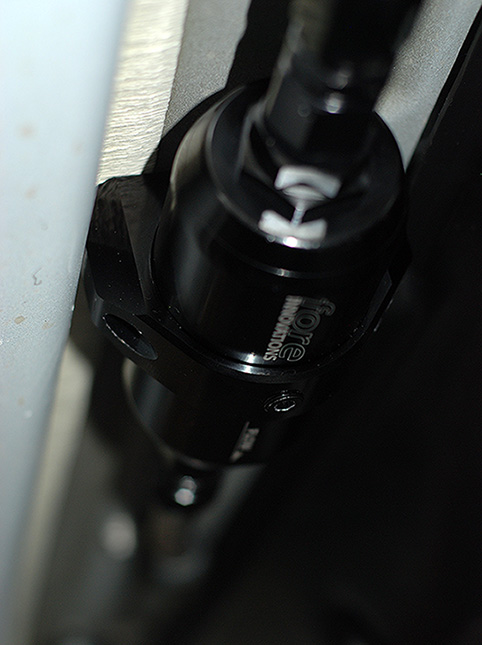
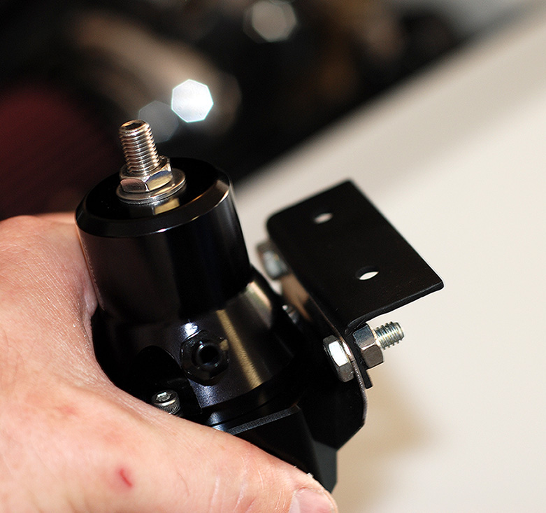
For the regulator, I decided to fab up a quick mount to work with the mount on the regulator.
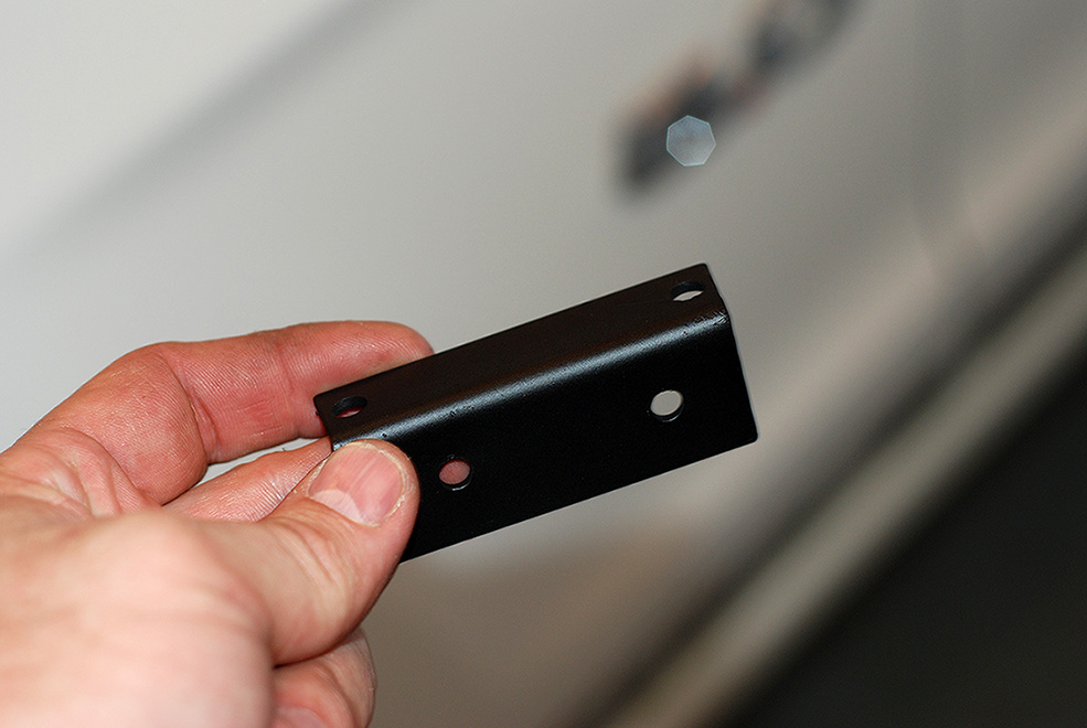
Since the sound tube was deleted, this left two existing holes for the bracket.
Now I just have to run the hoses to the rails and install the injectors!
Over all, the new PTFE fittings were relatively easy to assemble.
Here is the new PTFE line with the black "Conductive Carbon" inner core. This is approved for air craft and will not degrade over time or cause static like other PTFE line.
First step is to pull back the stainless steel so you have room for the Olive connector.
Next I installed the Olive between the stainless and PTFE inner hose.
Then I put the end fitting into my soft jaws in my vise with very little pressure and pushed on the hose to the fitting.
Then I turned the hose so it was facing up in the vise and tightened the fitting down with a 7/8" socket and ratchet.
Next up was to mount the filter. The filter comes with self tapping screws, but the floor pan where I wanted to mount it was very thick. So I drilled and tapped it.
Here are the screws I used to secure it to the bottom of the car.
I decided to mount the filter right behind the rocker panel on the drivers side for easy serviceability.
Here are the hoses hooked up to the hat.
I just followed the factory routings for ease of installation. Here's where it runs down from the front corner of the tank.
There are two plastic factory guards under the car that help protect the lines and I chose to run the hose under like the factory. You can see where I ran the feed line out for the filter.
Here I used another supplied cushion clamp and ran the line back under the factory panel.
Here is where the lines runs up the inner wheel well following the factory lines.
Then up into the engine bay behind the drivers side strut tower. I taped off the ends so nothing would get into them.
For the regulator, I decided to fab up a quick mount to work with the mount on the regulator.
Since the sound tube was deleted, this left two existing holes for the bracket.
Now I just have to run the hoses to the rails and install the injectors!
6/30/13, 07:23 AM
#16
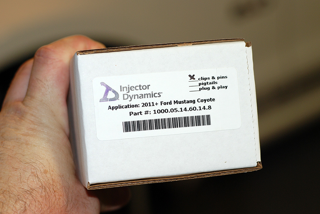
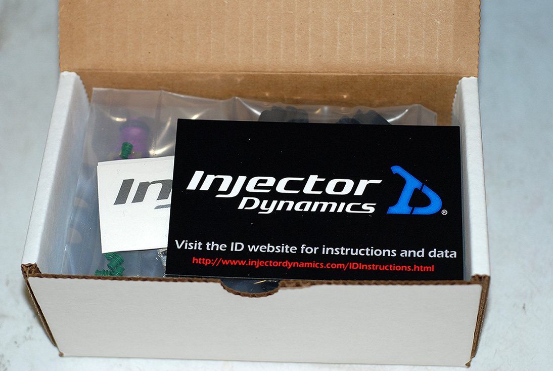
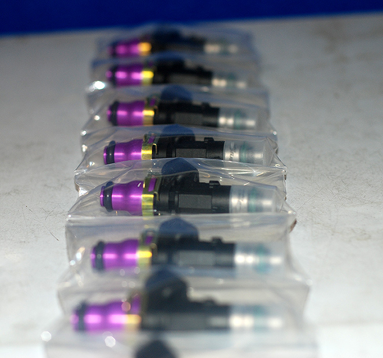
I received the final parts needed.
ID1000 Injectors. Thanks to Jared at Lethal! :rockon:
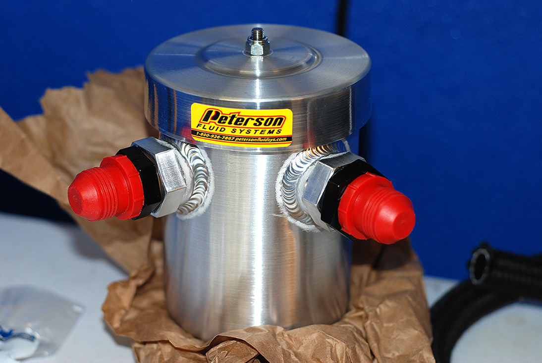
Also received my Peterson Fluid Systems catch can set up.
Thanks to my buddy Sergio "undfetd" and the guys at Power By The Hour! :thumbsup:
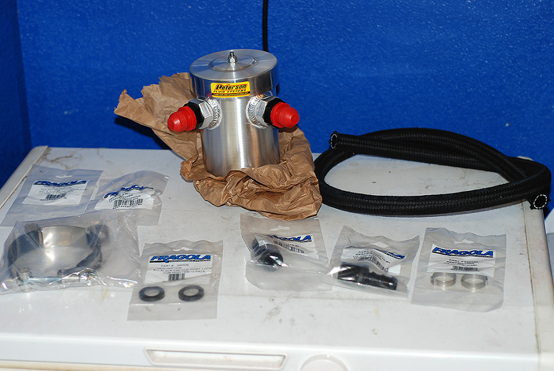
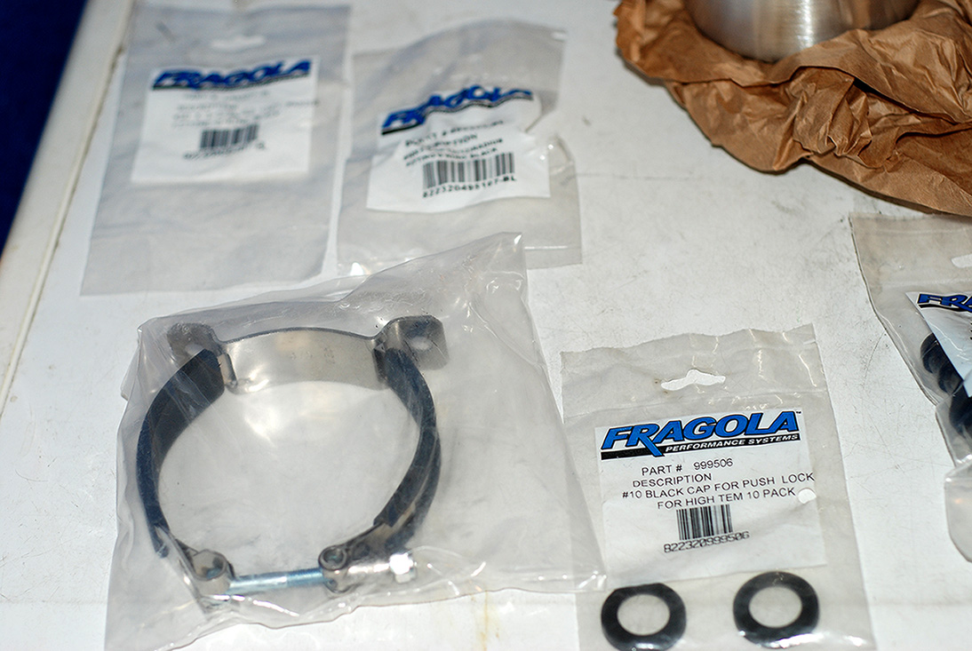
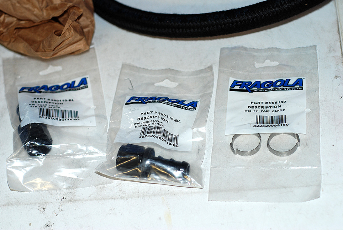
Misc bracket and fittings.
Hope to get this installed this weekend.
ID1000 Injectors. Thanks to Jared at Lethal! :rockon:
Also received my Peterson Fluid Systems catch can set up.
Thanks to my buddy Sergio "undfetd" and the guys at Power By The Hour! :thumbsup:
Misc bracket and fittings.
Hope to get this installed this weekend.
 6/30/13, 07:46 PM
#18
They are using Precision Turbo's now.
Should be very fun with the auto!
 6/30/13, 07:46 PM
#19
I did get a little more work done today.
Mocked up the fuel rails.
I used two 90* fittings on the front for the crossover.
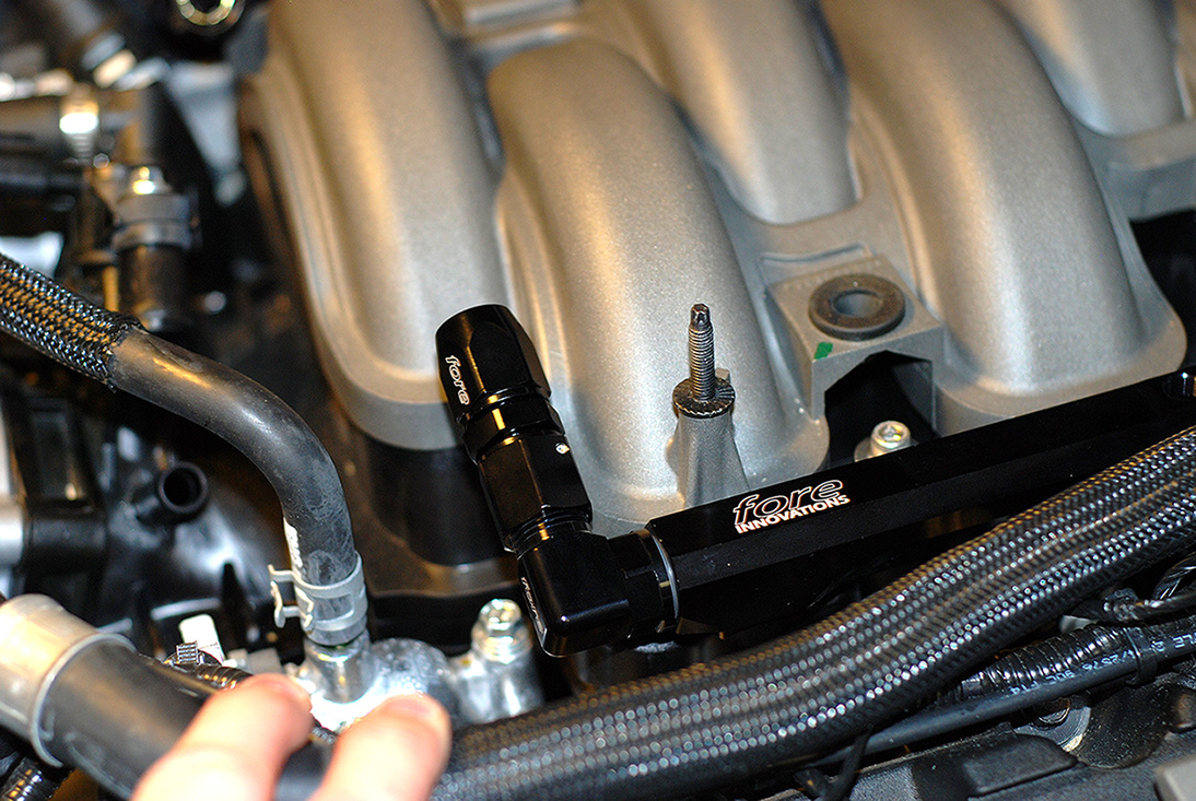
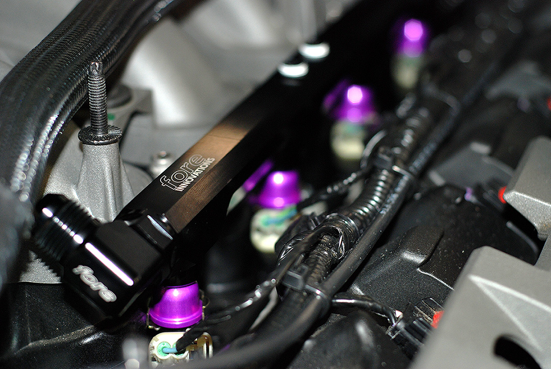
After tightening the fittings, I installed the ID1000's and bolted the rails down.
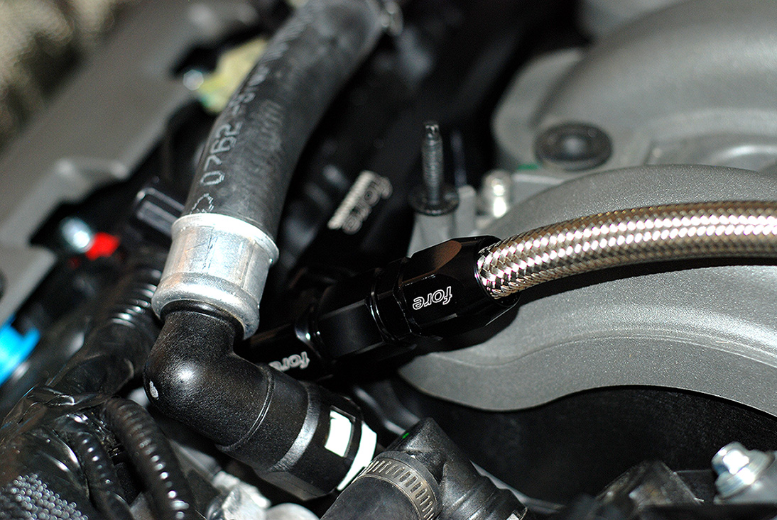
Then I had to make a line for the crossover. Here's a good shot of the fittings and line.
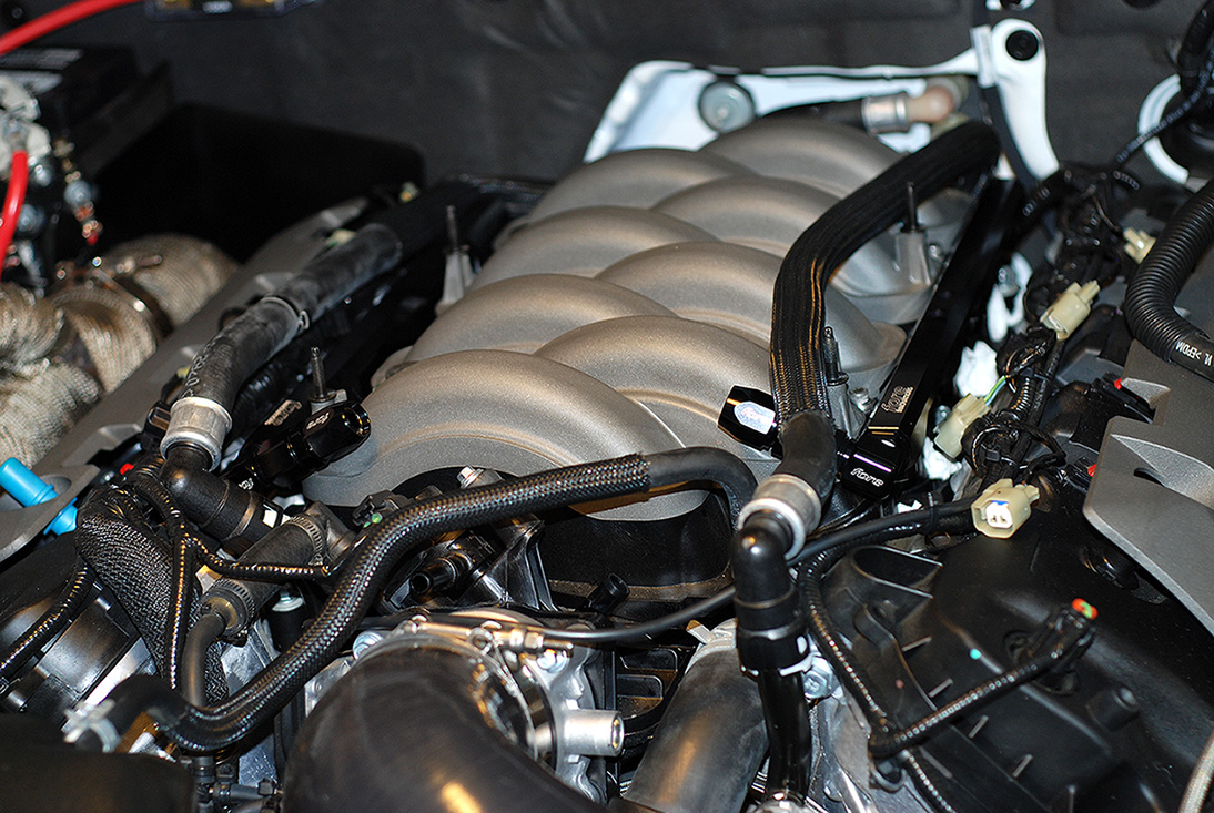
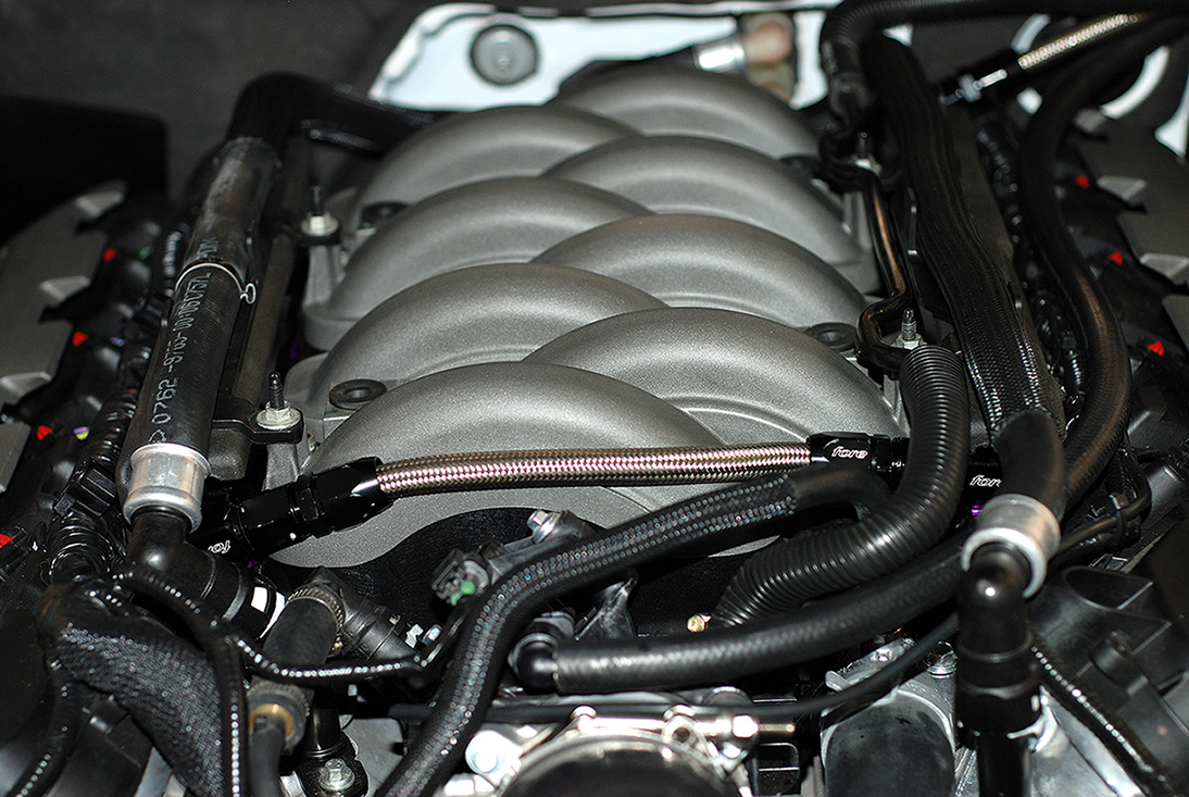
Got both rails and injectors installed. Foam covers back on the rails and heater lines back in place as well as the vacuum lines. I kept the crossover line short and sweet to keep clearance for the stock engine cover.
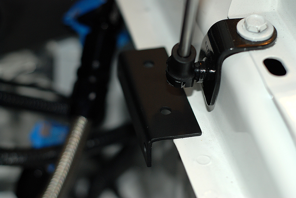
Here you can see the bracket I made for the regulator to bolt to the sound tube holes.

I would have this mounted but I need to get one more 90* fitting for the feed line from the regulator to the rails. I will order that tomorrow. Hopefully I will have it by next weekend.
Mocked up the fuel rails.
I used two 90* fittings on the front for the crossover.
After tightening the fittings, I installed the ID1000's and bolted the rails down.
Then I had to make a line for the crossover. Here's a good shot of the fittings and line.
Got both rails and injectors installed. Foam covers back on the rails and heater lines back in place as well as the vacuum lines. I kept the crossover line short and sweet to keep clearance for the stock engine cover.
Here you can see the bracket I made for the regulator to bolt to the sound tube holes.
I would have this mounted but I need to get one more 90* fitting for the feed line from the regulator to the rails. I will order that tomorrow. Hopefully I will have it by next weekend.