Wiring Fog Lights on a V6
 10/23/05, 01:50 PM
#1
Bullitt Member
Thread Starter
SCHEMATIC DIAGRAM: Provided by Flight96 and seen at post #16.
MATERIAL LIST: 30' of 18 gauge stranded copper wire; 25' of 14 gauge stranded copper wire; Two mini-fuse holders; 15-amp mini-fuse & 5-amp mini-fuse; SPST (Single Post Single Throw) Dash Switch; Relay, Blue & Yellow Terminals; Zip-ties, Electrical Tape
TOOL LIST: Soldering Iron and solder; Philips & Flat-head screw drivers; Socket Set; Drill & Bits; Knife; Floor Jack & Safety Stands; Crimper / Stripper Tool
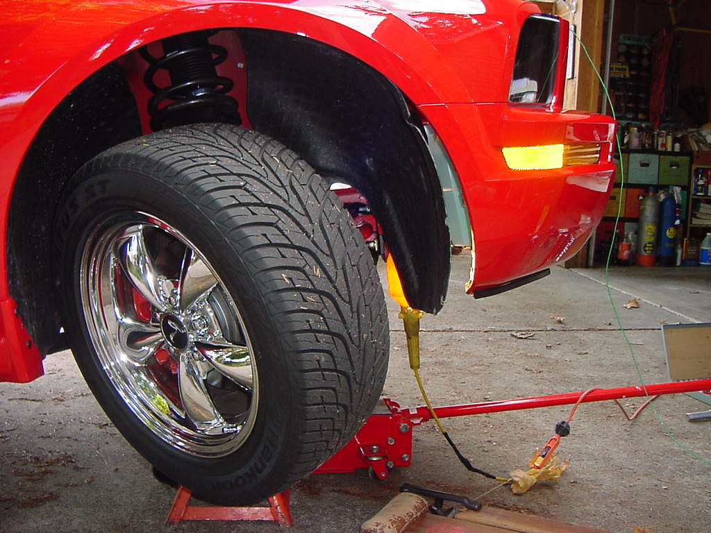
Step #1 of 9
Jack-up the car and loosen the right forward inner fender enough to get the right front side marker out of its socket. The fender fasteners that look like a Phillips head can be loosened with a � turn left, then the fasteners can be pulled-out by their heads.

MATERIAL LIST: 30' of 18 gauge stranded copper wire; 25' of 14 gauge stranded copper wire; Two mini-fuse holders; 15-amp mini-fuse & 5-amp mini-fuse; SPST (Single Post Single Throw) Dash Switch; Relay, Blue & Yellow Terminals; Zip-ties, Electrical Tape
TOOL LIST: Soldering Iron and solder; Philips & Flat-head screw drivers; Socket Set; Drill & Bits; Knife; Floor Jack & Safety Stands; Crimper / Stripper Tool
Step #1 of 9
Jack-up the car and loosen the right forward inner fender enough to get the right front side marker out of its socket. The fender fasteners that look like a Phillips head can be loosened with a � turn left, then the fasteners can be pulled-out by their heads.
Last edited by Gearhead; 5/11/08 at 08:05 PM. Reason: update photo link
 10/23/05, 01:51 PM
#2
Bullitt Member
Thread Starter
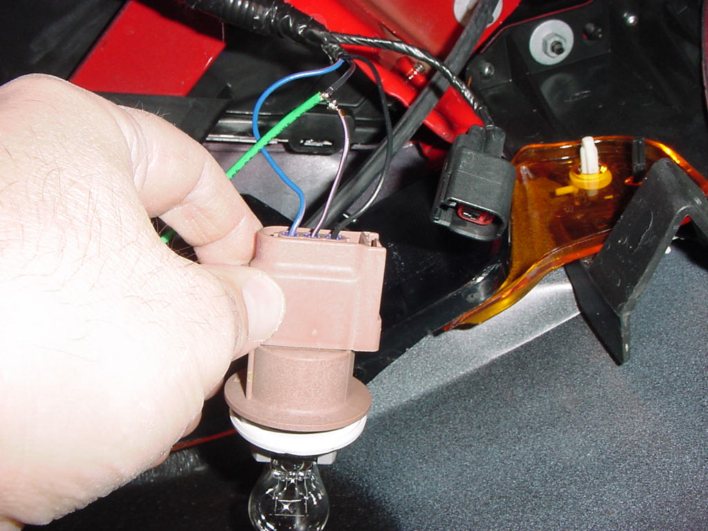
Step #2 of 9
Solder onto the middle terminal of the lamp (this is the parking lamp circuit), so that you can use this wire as the switching means. I personally like to just remove the outer insulation, wrap the 18-gauge stranded copper wire onto it, and solder it for a reliable connection. 18-gauge wire is the minimum wire size that you should use, as lighter gauges are not physically strong enough to handle well the tensile loads that may occur as you install and subsequently work on your car. As far as current is concerned, 18-gauge is well suited for this task. Wrap the connection well with electrical tape. With this set-up, your Fog Lights will go off when you shut the headlight switch off, and can be on with the Parking Light Circuit. Bring this wire up to the area near the right side of the radiator, and solder-in an in-line fuse holder. Use a 5-amp fuse for this switching means circuit (see the photo in Step #5 to see the 5-amp fuse holder).

Solder onto the middle terminal of the lamp (this is the parking lamp circuit), so that you can use this wire as the switching means. I personally like to just remove the outer insulation, wrap the 18-gauge stranded copper wire onto it, and solder it for a reliable connection. 18-gauge wire is the minimum wire size that you should use, as lighter gauges are not physically strong enough to handle well the tensile loads that may occur as you install and subsequently work on your car. As far as current is concerned, 18-gauge is well suited for this task. Wrap the connection well with electrical tape. With this set-up, your Fog Lights will go off when you shut the headlight switch off, and can be on with the Parking Light Circuit. Bring this wire up to the area near the right side of the radiator, and solder-in an in-line fuse holder. Use a 5-amp fuse for this switching means circuit (see the photo in Step #5 to see the 5-amp fuse holder).
Last edited by Gearhead; 5/11/08 at 08:08 PM. Reason: update photo link
10/23/05, 01:52 PM
#3
Bullitt Member
Thread Starter
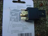
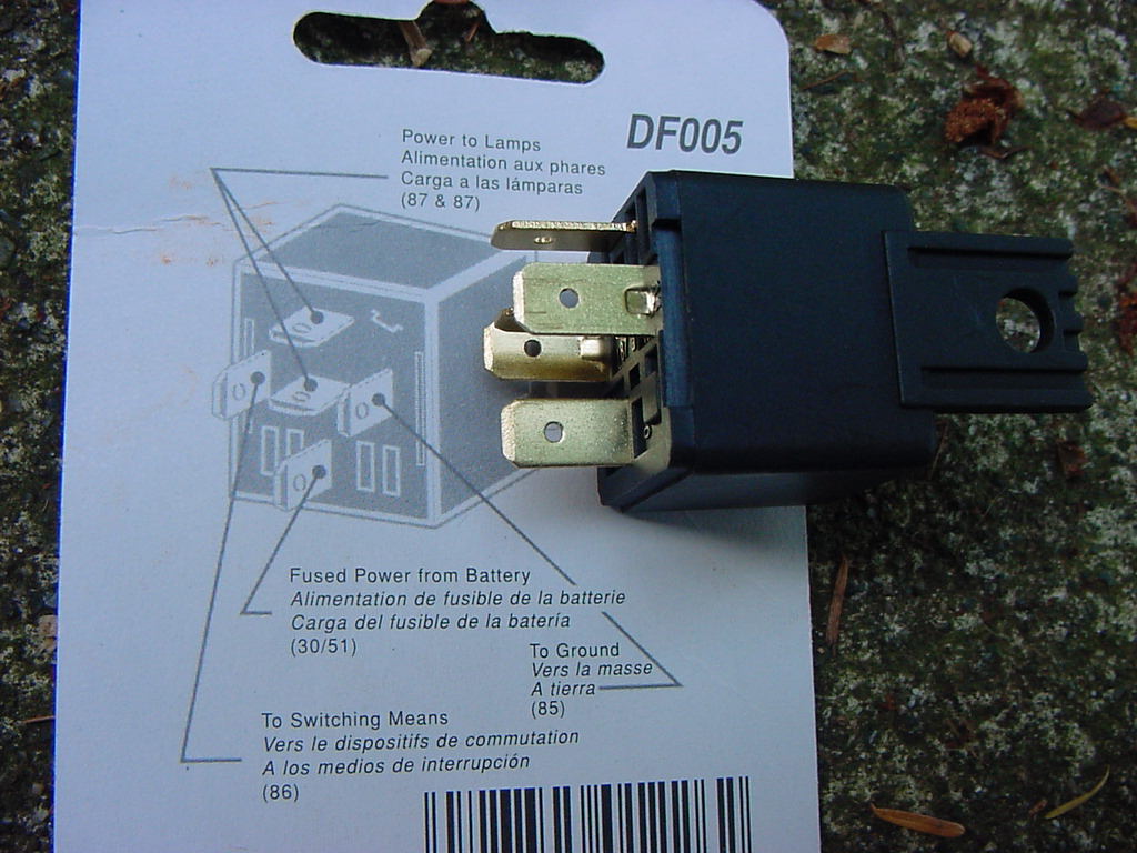
Step #3 of 9
This photo shows a good relay to select for your Fog Lights, and shows its instruction card. Inexpensive, this particular one came from Schucks Auto. All wiring will meet-up at this relay.
(A four terminal relay could also be substituted, wherein you would common together both fog lights at a single "Power to Lamps" terminal.)
Last edited by Gearhead; 5/11/08 at 08:10 PM. Reason: update photo link
10/23/05, 01:53 PM
#4
Bullitt Member
Thread Starter
Step #4 of 9
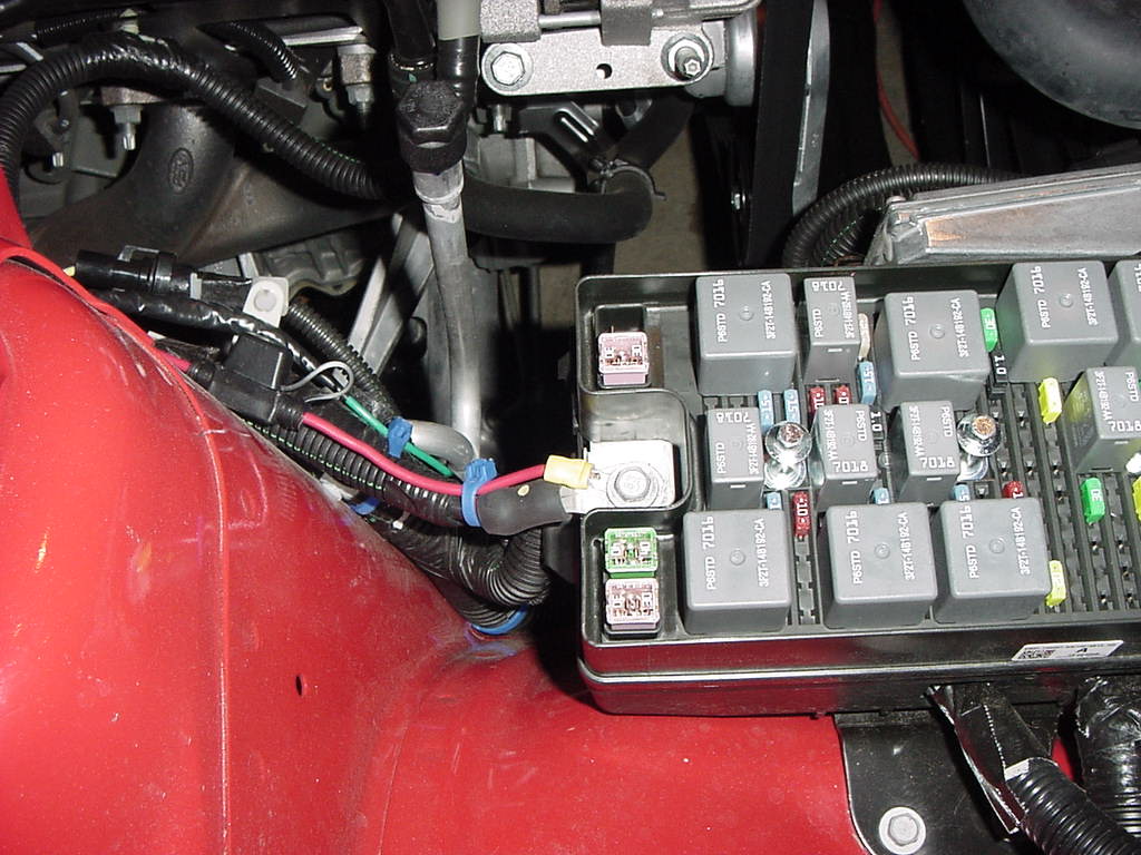
Using 14-gauge stranded copper wire (larger is OK but not required) strip & solder the terminal end that will fit on the power-supply side of the Ford Power Box. You must solder the free end of stranded copper wire, because a simple crimp terminal would smash-out the connector and mechanically, it would be an unreliable grip. In other words, you must have something solid upon which to crimp. Also, solder in an in-line fuse holder reasonably close to this point. You will need a 15-amp fuse for this circuit. Solder all twisted connections and wrap well with electrical tape. Route the 14-gauge wire under the Ford Power Box, zip tying onto other harnesses, and leave room to do other work, not taking tight short cuts in the wiring path.
ALSO Please see further explanation regarding this Step at posts #18 & #19.
Last edited by Gearhead; 5/11/08 at 08:12 PM. Reason: update photo link
10/23/05, 01:54 PM
#5
Bullitt Member
Thread Starter
Step #5 of 9
Temporarily connect the relay onto a mounting bolt that Ford provides to hold the lower forward side of the Ford Power Box. You may have to drill-out the mounting hole of the relay to get it to accept the bolt diameter. Keeping your final wiring comb-out in mind, now bring the relay up to where you can work upon it. Terminate the 15-amp circuit to the fused power from battery relay lug. Using one of the grounding studs (as seen in the lower left of the photo), provide a 14-gauge grounding wire and hook that up to the ground lug of the relay. At this point, terminate the two wire pairs, which will go to your fog lights, commoning the negative wires to ground, and using (in this case) the two separate Power to Lamp lugs for the positive leads.
Temporarily connect the relay onto a mounting bolt that Ford provides to hold the lower forward side of the Ford Power Box. You may have to drill-out the mounting hole of the relay to get it to accept the bolt diameter. Keeping your final wiring comb-out in mind, now bring the relay up to where you can work upon it. Terminate the 15-amp circuit to the fused power from battery relay lug. Using one of the grounding studs (as seen in the lower left of the photo), provide a 14-gauge grounding wire and hook that up to the ground lug of the relay. At this point, terminate the two wire pairs, which will go to your fog lights, commoning the negative wires to ground, and using (in this case) the two separate Power to Lamp lugs for the positive leads.

Last edited by Gearhead; 5/11/08 at 08:16 PM. Reason: update photo link
10/23/05, 01:55 PM
#6
Bullitt Member
Thread Starter
Step #6 of 9
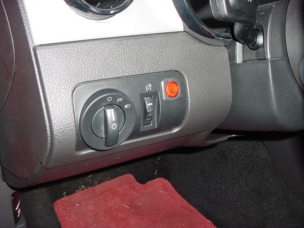
Remove your headlight switch by pushing it out from the backside. I did have a clip flick-off, but it is no big deal; just slide it back upon its grooved slot. Unplug the switch and the dimmer. This will make the headlights turn on, but not to worry; they will time-out after 15 minutes battery saver mode kicks-in. Use a small drill to start a pilot hole for your switch. Do not use a big drill bit, or you will tear the plastic panel when the drill flutes dig-in. Also, use wire cutters and needle nose pliers to break-off the plastic fins inside the cover, as required. Ream out the hole with a drill bit and a round file to get a size large enough to accept your switch. My switch is a $4 SPST (Single Post Single Throw) from Radio Shack.

Remove your headlight switch by pushing it out from the backside. I did have a clip flick-off, but it is no big deal; just slide it back upon its grooved slot. Unplug the switch and the dimmer. This will make the headlights turn on, but not to worry; they will time-out after 15 minutes battery saver mode kicks-in. Use a small drill to start a pilot hole for your switch. Do not use a big drill bit, or you will tear the plastic panel when the drill flutes dig-in. Also, use wire cutters and needle nose pliers to break-off the plastic fins inside the cover, as required. Ream out the hole with a drill bit and a round file to get a size large enough to accept your switch. My switch is a $4 SPST (Single Post Single Throw) from Radio Shack.
Last edited by Gearhead; 5/11/08 at 08:20 PM. Reason: update photo link
10/23/05, 01:55 PM
#7
Bullitt Member
Thread Starter
Step #7 of 9
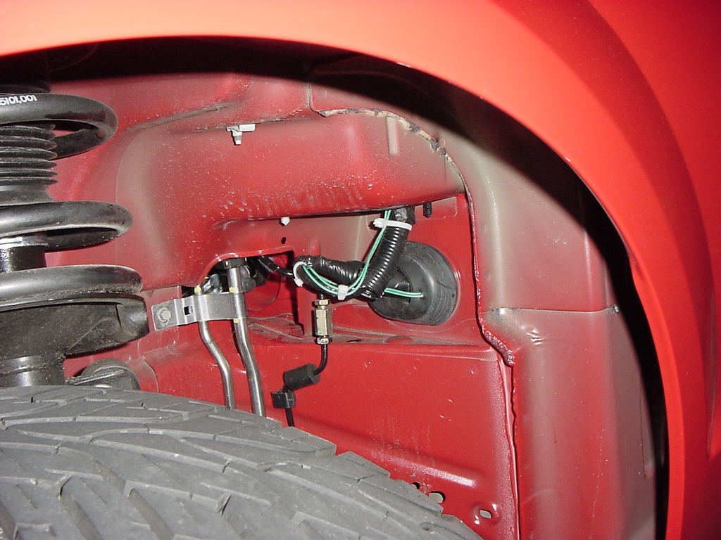
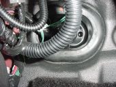
Jack-up the car and remove the left aft inner fender. There you will see the firewall grommet, which you can cut a very small cross slit into, and this will be your wire pass-through.

Jack-up the car and remove the left aft inner fender. There you will see the firewall grommet, which you can cut a very small cross slit into, and this will be your wire pass-through.
Last edited by Gearhead; 5/11/08 at 08:21 PM. Reason: update photo link
10/23/05, 01:56 PM
#8
Bullitt Member
Thread Starter
Step #8 of 9
Route two 18-gauge wires from your dash switch, leaving plenty of slack for future work. Using existing bundle as zip tie points, pass through the firewall grommet and route up to the engine bay. This view is from under the driver's dash going through that grommet.
Route two 18-gauge wires from your dash switch, leaving plenty of slack for future work. Using existing bundle as zip tie points, pass through the firewall grommet and route up to the engine bay. This view is from under the driver's dash going through that grommet.
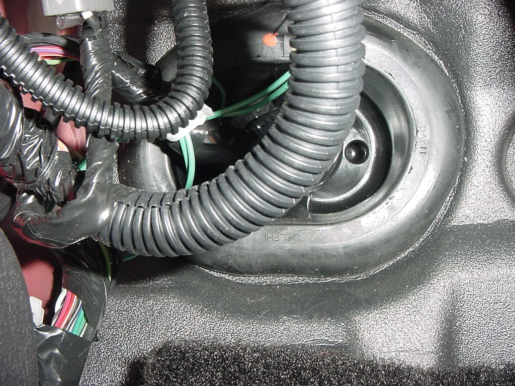
Last edited by Gearhead; 5/11/08 at 08:22 PM. Reason: update photo link
10/23/05, 01:57 PM
#9
Bullitt Member
Thread Starter
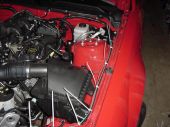
Step #9 of 9
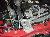
Route and secure the pair of 18-gauge wires along the engine hood release cable. After you remove the top radiator cover piece, which crosses over the radiator, continue to tie your pair of 18-gauge wires onto the harness, which crosses in front of the radiator. Terminate one of these 18-gauge wires onto the other end of the 5-amp fuse holder, and terminate the other 18-gauge wire to the switching means terminal of the relay. Attach your relay to the forward side of the Ford Power Box, and you are done with your Fog Light Wiring.
Fog Light Grille by Street Scene:
Route and secure the pair of 18-gauge wires along the engine hood release cable. After you remove the top radiator cover piece, which crosses over the radiator, continue to tie your pair of 18-gauge wires onto the harness, which crosses in front of the radiator. Terminate one of these 18-gauge wires onto the other end of the 5-amp fuse holder, and terminate the other 18-gauge wire to the switching means terminal of the relay. Attach your relay to the forward side of the Ford Power Box, and you are done with your Fog Light Wiring.

Fog Light Grille by Street Scene:
Last edited by Gearhead; 5/11/08 at 08:25 PM. Reason: update photo link
10/23/05, 06:32 PM
#10
V6 Member

Join Date: February 13, 2005
Posts: 83
Likes: 0
Received 0 Likes
on
0 Posts
Man, I wish I knew even a little bit about what gearhead is talking about in these instructions! They sound like they'd be really clear except for the fact that they are basically in another language...  'Terminate the 15-amp circuit to the “fused power from battery” relay lug'.
'Terminate the 15-amp circuit to the “fused power from battery” relay lug'.
10/23/05, 06:58 PM
#11
That's like 10x more complicated than it needs to be. My T2 grill came with a harness and I didn't have to do any of that crap. I just had to route it to the battery and the switch. That's it.
10/23/05, 07:40 PM
#12
Originally posted by Jimp@October 23, 2005, 8:01 PM
That's like 10x more complicated than it needs to be. My T2 grill came with a harness and I didn't have to do any of that crap. I just had to route it to the battery and the switch. That's it.
That's like 10x more complicated than it needs to be. My T2 grill came with a harness and I didn't have to do any of that crap. I just had to route it to the battery and the switch. That's it.
Same here! I ran mine to the battery.
10/24/05, 12:37 AM
#14
Bullitt Member
Thread Starter
Yes, the Fogs will shut-off when the headlamp switch is in the off position.
The Fog Lights can only be turned on when the Fog switch on the dash is “up” and the headlamp switch is in one of three modes:
1.) Parking Lights
2.) Low Beams
3.) High Beams
The advantage with using the Parking Light Circuit to power the “switching means” circuit is that you will get an audible chime if you leave the Fog lights on.
10/26/05, 12:24 PM
#15
Mach 1 Member

Join Date: October 20, 2004
Location: Victoria Canada
Posts: 728
Likes: 0
Received 0 Likes
on
0 Posts
Thanks for the info...is there a possibility of getting a wiring diagram for these? I put Blazer C120 lights in the grille but have not yet wired them. I have been looking for some good,simple instructions.Im just a stupid car painter...NOT an electrition... This seems to be the most complete ones Ive read yet...I Don't quite understand where your connecting to on the "power-supply side of the Ford Power Box"?? Is that where the bolt is at the back of the box in the pic you supplied?
The switch you are using in the dash, is it a 2 or 3 pole switch? You say your running 2 leads off the dash switch, 1 to the switch side of the relay and the other to the Fused side of the lead to the Power box...is this right?
The switch you are using in the dash, is it a 2 or 3 pole switch? You say your running 2 leads off the dash switch, 1 to the switch side of the relay and the other to the Fused side of the lead to the Power box...is this right?
10/26/05, 02:58 PM
#16
Mach 1 Member
Join Date: October 20, 2004
Location: Victoria Canada
Posts: 728
Likes: 0
Received 0 Likes
on
0 Posts
OK....after further review.....I sound like an NFL ref........I think I have this figured out... :scratch: Does this look like what you are saying???
Its a crude schematic but hey...all I have is MS paint to work with here!! And like I mentioned earlier...Im just a dumb car painter !!! :crazy:
Its a crude schematic but hey...all I have is MS paint to work with here!! And like I mentioned earlier...Im just a dumb car painter !!!
:crazy:
10/26/05, 04:20 PM
#17
Bullitt Member
Thread Starter
That is one very nice schematic! Great job. It describes the wiring perfectly. That hopefully will clarify these instructions for others too.
Many thanks, Brian.
Many thanks, Brian.
10/26/05, 05:57 PM
#19
Bullitt Member
Thread Starter
You connect to the input terminal on the aft side of the power box. This is where the cable that comes directly from the battery hooks up as well. In the photo on step #4 of 9, this is the red wire with the yellow lug and the blue zip-tie. It is also part of the 15 amp in-line fuse pig-tail. It is exactly as you diagram in the photo above as well!
10/26/05, 09:00 PM
#20
Shelby GT500 Member
Join Date: January 30, 2004
Location: Riverside, CA
Posts: 2,916
Likes: 0
Received 0 Likes
on
0 Posts
The diagram is all I needed to visualize it (Flight96, Gearhead  ), really good (extremely detailed
  ) writeup though.
The fogless look grew on me now though, I guess it was all the figuiring on which route I was willing to take and the $. That's performance mod money now though
), really good (extremely detailed ) writeup though. The fogless look grew on me now though, I guess it was all the figuiring on which route I was willing to take and the $. That's performance mod money now though